
Daylighting and illumination system of building and daylighting and illumination method for building

A technology for lighting systems and buildings, which is applied in the direction of light guides, lighting devices, non-electric lighting devices, etc. of the lighting system, can solve the problems of increasing energy consumption, and achieve the effects of energy saving, reasonable structure and sufficient light

Active Publication Date: 2015-04-01
BEIJING ARITIME INTELLIGENT CONTROL
View PDF6 Cites 4 Cited by
  • Summary
  • Abstract
  • Description
  • Claims
  • Application Information

AI Technical Summary

Problems solved by technology

These rooms still need to use artificial electric lighting even during the day and when there is sufficient outdoor light, which increases energy consumption

Method used


Image

  • Daylighting and illumination system of building and daylighting and illumination method for building

Examples


Embodiment 1

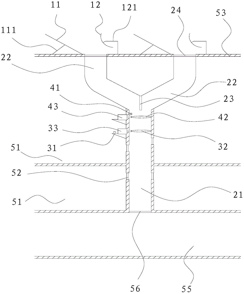
[0028] The preferred embodiment discloses a building daylighting and lighting system. Such as figure 1 As shown, the lighting system mainly includes a light reflection device and a light pipe. Wherein, the light reflection device includes at least one set of reflector assemblies; the light guide includes a main pipeline 21 arranged in the building to be illuminated, and two branch roads 22 are arranged between the main pipeline 21 and the outer wall 53 of the building to be illuminated, A Y-shaped structure is formed; a double-sided reflector 23 is provided at the junction of the two branches 22 to ensure that sunlight can continue to be transmitted in the light pipe.

[0029] A light entrance 24 is formed between each branch 22 and the outer wall 53 , and a set of reflector assemblies is arranged on the outside of each light entrance 24 . Each set of reflector assemblies includes a reflective flat mirror 11 and a reflective convex mirror 12 oppositely arranged on both sides...

Embodiment 2

[0040] This preferred embodiment discloses a building daylighting and lighting system, the structure of which is basically the same as that of the preferred embodiment 1. The lighting system includes a light reflection device and a light guide tube; the light reflection device is used to reflect external light into the light guide tube; the light guide tube extends into the interior of the building to be illuminated, and at least one window is opened on the side wall of the light guide tube , the window is used to penetrate light into the room to be illuminated.

[0041] The difference is that: the daylighting lighting system may not include infrared filtering device and / or ultraviolet filtering device, with the primary purpose of assisting the lighting of rooms lacking sunlight; even if infrared filtering device and / or ultraviolet filtering device is installed, these two devices The specific structure is not limited, as long as it can achieve the effect of reducing infrared r...


PUM


Abstract

The invention discloses a daylighting and illumination system of a building and a daylighting and illumination method for the building, belongs to the field of daylighting and illumination devices and methods for the buildings, and aims at solving the problem that the illumination energy consumption of a room lack of sunshine radiation. The daylighting and illumination system of the building comprises a light ray reflection device and a light guide pipe, wherein the light ray reflection device is used for reflecting external light rays into the light guide pipe; the light guide pipe extends into the building to be illuminated; at least one window is formed in the side wall of the light guide pipe and is used for transmitting the light rays into a room to be illuminated. The invention also discloses a daylighting and illumination method for the building based on the daylighting and illumination system. The daylighting and illumination system and the daylighting and illumination method for the building can be used for assisting in illumination of the room lack of light rays for a long time; energy is saved, and the illumination effect is good.

Description

technical field [0001] The invention relates to a building lighting system and a building lighting method based on the lighting system. Background technique [0002] Buildings (especially high-rise buildings) usually have rooms that do not see sunlight all the year round, such as basements, underground passages, and underground shopping malls. Even in the daytime and when the outdoor light is sufficient, these rooms still need to use artificial electric lighting, which increases energy consumption. Contents of the invention [0003] One object of the present invention is to provide a building lighting system with reasonable structure, low cost, sufficient light and good lighting effect. [0004] Another object of the present invention is to propose a lighting method for buildings that saves energy and has good lighting effects. [0005] For reaching this purpose, on the one hand, the present invention adopts following technical scheme: [0006] A building lighting light...

Claims


Application Information

Patent Timeline
IPC IPC(8): F21S11/00F21V14/08F21V8/00F21V7/05F21V5/04
CPCF21S11/007F21V7/0033F21V14/08F21V23/0442
Inventor 邱忠义麻硕谢鹏赵宏
Owner BEIJING ARITIME INTELLIGENT CONTROL
Learn More