
Gas injection valve with lubricating mechanism

A gas injection and lubricating mechanism technology, applied in the direction of valve lift, valve details, valve device, etc., can solve the problems of increasing the movement resistance of the valve stem, affecting the service life, prolonging the response time, etc., to achieve large gas injection flow rate and response speed Fast and simple production process

Active Publication Date: 2015-04-01
WEIFANG LICHUANG ELECTRONICS TECH
View PDF6 Cites 0 Cited by
  • Summary
  • Abstract
  • Description
  • Claims
  • Application Information

AI Technical Summary

Problems solved by technology

[0005] Due to the moving parts in the valve stem, there is sliding friction between the valve stem and the valve body of the above-mentioned various gas injection valves. Due to the lack of a reasonable lubrication structure, the sliding friction between the valve stem and the valve body not only increases the The movement resistance prolongs the response time, and it is easy to cause excessive wear of the valve stem, which affects the service life

Method used


Image

  • Gas injection valve with lubricating mechanism
  • Gas injection valve with lubricating mechanism

Examples


Embodiment Construction

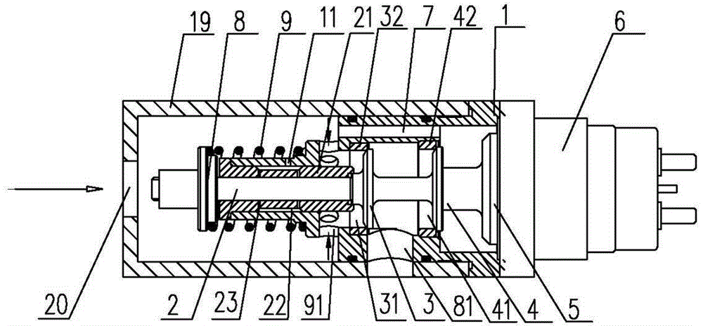
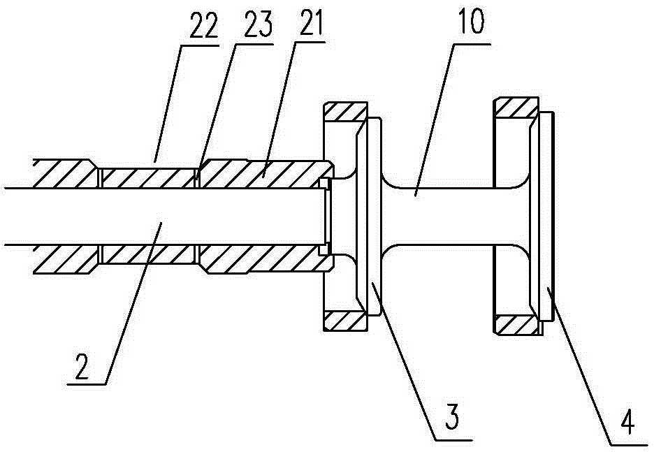
[0014] Such as figure 1 As shown, the gas injection valve with a lubricating mechanism of the present invention includes a valve body 1, a valve stem 2 installed in the valve body 1, valve plates 3, 4 coaxially arranged with the valve stem 2, and a movable armature 5, Electromagnetic coil 6, the valve stem 2 is a columnar structure, a valve stem bushing 21 is arranged between the valve stem 2 and the valve body 1, the valve stem bushing 21 is fixedly connected with the valve body 1, the valve stem 2 and the valve body 1 are fixedly connected. The valve stem sleeve 21 is a sliding fit for axial movement; an oil storage tank 22 with an annular structure is arranged between the outer surface of the valve stem sleeve 21 and the valve body 1, and the oil storage tank 22 can be as figure 1 , figure 2 It is set on the outer surface of the valve stem bushing 21 as shown, and it can also be arranged on the inner wall of the valve body 1 in contact with the valve stem bushing 21. The ...


PUM


Abstract

The invention relates to a gas injection valve, in particular to the gas injection valve with a lubricating mechanism. The gas injection valve comprises a valve body, a valve rod mounted in the valve body, a valve plate and a moving armature coaxial with the valve rod, and an electromagnetic coil, wherein the valve rod is of a columnar structure; a valve rod sleeve is arranged between the valve rod and the valve body and is fixedly connected with the valve body; an oil storage tank with an annular structure is arranged between the outer surface of the valve rod sleeve and the valve body; an oil way communicated with an inner cavity of the valve rod sleeve is arranged in the oil storage tank; an oil filling port communicated with the oil storage tank is formed in the valve body. The gas injection valve is of a double-valve gas inlet structure formed integrally, and the lubricating mechanism is arranged between the valve rod and the valve body; the valve rod is small in frictional resistance, long in service life, large in gas injection flow, high in response speed and easy to assemble.

Description

technical field [0001] The invention relates to a gas injection valve, in particular to a gas injection valve with a lubricating mechanism. Background technique [0002] Injection volume, response time, and life are important parameters to measure the quality of gas injection valves. Due to the low density of gas, the diameter of the valve required when the injection flow rate is large is also large, but the large gas working pressure acts on the gas injection valve. On the valve, it will hinder the opening and closing movement of the valve and restrict the response time. Therefore, high-speed electromagnetic gas injection valves driven by electromagnetics can generally only adapt to smaller flow requirements and lower gas pressure conditions, and cannot meet high-speed quantitative injection under larger flow and higher pressure requirements. [0003] The EGR valve produced by Delphi Company in the United States adopts balanced double valve intake, the diameters of the two...

Claims


Application Information

Patent Timeline
Patent Type & Authority Applications(China)
IPC IPC(8): F16K1/00F16K1/36F16K31/06F16K27/02
CPCF16K1/00F16K1/36F16K27/02F16K31/06
Inventor 吴龙龙
Owner WEIFANG LICHUANG ELECTRONICS TECH
Learn More