Eureka AIR delivers breakthrough ideas for toughest innovation challenges, trusted by R&D personnel around the world.

Welding process for ensuring smooth transition and molding of ellipsoidal circular seam and auxiliary welding clamp thereof

A welding process and smooth transition technology, applied in auxiliary welding equipment, welding/cutting auxiliary equipment, auxiliary devices, etc., can solve the problems affecting the charge amount and performance of the shell, so as to adapt to mass production and the method is simple and easy line effect

Inactive Publication Date: 2015-04-01
湖北三江航天江北机械工程有限公司
View PDF7 Cites 34 Cited by
  • Summary
  • Abstract
  • Description
  • Claims
  • Application Information

AI Technical Summary

Problems solved by technology

[0002] The combustion chamber shell is an important part of the rocket engine. It is used to store the powder and ignite the powder. During the working process of the rocket, it is subjected to high temperature and high pressure. It is generally welded by joints, ellipsoids and cylinders. The ellipsoid and After the girth weld of the joint is welded in the usual way, due to welding shrinkage and deformation, the position of the weld seam will show a large shrinkage depression to the inside of the shell, which will affect the charge and performance of the shell

Method used


Image

  • Welding process for ensuring smooth transition and molding of ellipsoidal circular seam and auxiliary welding clamp thereof
  • Welding process for ensuring smooth transition and molding of ellipsoidal circular seam and auxiliary welding clamp thereof

Examples


Embodiment Construction

[0026] The present invention will be further described in detail below in conjunction with the accompanying drawings and specific embodiments.

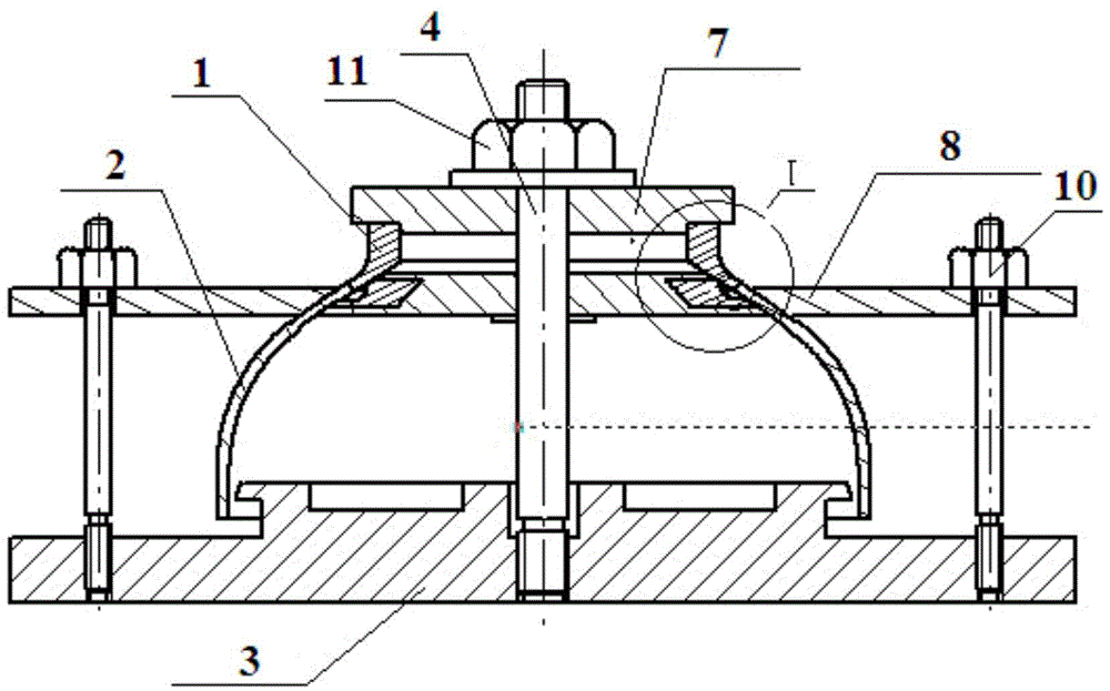
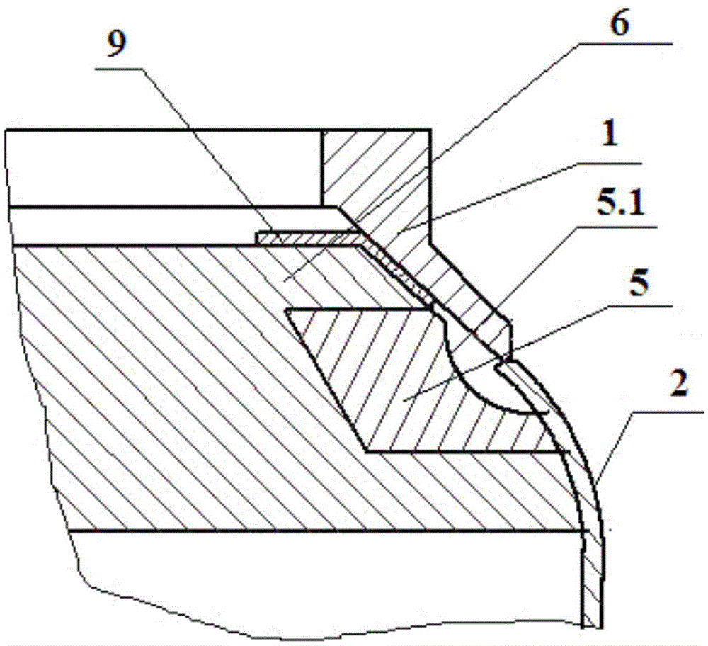
[0027] figure 1 It is the auxiliary welding jig and assembly diagram of the present invention. figure 2 It is a partial enlarged view of the shell joint and the girth weld of the ellipsoid.

[0028] From figure 1 , 2 It can be seen that before welding the combustion chamber shell joint 1 and the ellipsoid 2, the welding groove of the misaligned butt joint must be preset first, and the structure is as follows figure 1 , 2 As shown, the end faces of the ellipsoid 2 and the shell joint 1 to be welded have a blunt edge of 1mm and a unilateral bevel of 36° to ensure that the cross-sectional diameter of the shell joint 1 is Greater than the cross-sectional diameter of the ellipsoid 2, that is, the downward projection of the inner wall of the ellipsoid 2 at the joint is located on the inner surface of the downward projection of the inn...


PUM


Abstract

The invention discloses a welding process for ensuring smooth transmission and molding of an ellipsoidal circular seam. The welding process comprises the following steps: 1) pre-setting a welding groove structure; 2) assembling a joint and an ellipsoid to an auxiliary welding clamp as follows: butting the ellipsoid with a to-be-welded end surface of the joint, adhering the ellipsoid with the lower part of a positioning block fixed on a core rod by virtue of an ellipsoidal pressure plate, adhering the joint with the upper part of the positioning block by virtue of a joint pressure plate, and ensuring a circular seam to-be-welded part of the ellipsoid and the joint to be corresponding to an arc-shaped groove on a ring-shaped copper pad in the middle of the positioning block; 3) respectively performing positioned welding, non-wired backing welding, wired cosmetic welding, non-wired re-melting welding; and 4) slowly cooling and performing annealing thermal treatment. The invention further discloses an auxiliary welding clamp designed for realizing the method. By pre-setting the welding groove structure and the auxiliary welding clamp, dislocation caused by welding shrinkage of the ellipsoidal surface can be balanced out reversely, and the inner surface of the welding seam can be ensured to be molded very well.

Description

technical field [0001] The invention belongs to the field of welding technology, and in particular relates to a welding process and an auxiliary welding fixture for ensuring the smooth transition forming of circular seam welding, in particular to a welding process and an auxiliary welding fixture for ensuring the smooth transition forming of the circular seam welding of the ellipsoidal surface of a combustion chamber shell . Background technique [0002] The combustion chamber shell is an important part of the rocket engine. It is used to store the powder and ignite the powder. During the working process of the rocket, it is subjected to high temperature and high pressure. It is generally welded by joints, ellipsoids and cylinders. The ellipsoid and After the girth weld of the joint is welded in the usual way, due to welding shrinkage and deformation, the position of the weld seam will show a large shrinkage depression to the inside of the shell, which will affect the charge...

Claims


Application Information

Patent Timeline
IPC IPC(8): B23K9/167B23K9/235B23K33/00B23K37/04
CPCB23K9/167B23K9/028B23K9/235B23K33/00B23K37/0435
Inventor 赵冬旭李伟王明坤李青艳
Owner 湖北三江航天江北机械工程有限公司
Why Eureka
Eureka Blog
Learn More