
a short circuit transition co 2 Apparatus and method for welding synchronous pulsed magnetic field control

A technology of short-circuit transition and magnetic field generating device, which is applied in the direction of manufacturing tools, welding equipment, arc welding equipment, etc., which can solve the problems of increased spatter, reduced spatter, and inability to ensure synchronization, etc., and achieves the effect of reducing hindrance

Active Publication Date: 2017-01-11
SHENYANG POLYTECHNIC UNIV
View PDF2 Cites 0 Cited by
  • Summary
  • Abstract
  • Description
  • Claims
  • Application Information

AI Technical Summary

Problems solved by technology

From the perspective of welding materials and shielding gas, although the use of flux-cored wires containing rare earth (REM) trace elements or K, Na, Ba and other activated elements or the application of CO 2 with Ar or CO 2 with Ar, He and O 2 Although the mixed shielding gas (T.I.M.E. welding) improved the arc shape and achieved the effect of reducing spatter, it lost the CO 2 Due to the inherent economic characteristics of welding, the welding cost is greatly increased
In terms of welding equipment, waveform control technologies such as surface tension transition (STT), controlled liquid bridge transition (CBT) or cold metal transition (CMT) have achieved good results, which are suitable for thin wire thin plate welding, but have not yet been solved. The fundamental contradiction is that the contraction transition of the liquid bridge requires a large current, and the reduction of splashing requires a small liquid bridge current, especially at medium currents and high arc voltages. can't solve it
However, most of the above-mentioned external magnetic fields are based on constant and disordered introduction methods, without considering the application of magnetic fields of different strengths or frequencies at different stages of short-circuit transition, and cannot guarantee that the magnetic field is synchronized with each droplet transition process.
In addition, the magnetic control device must have a wide adjustment range of external magnetic field parameters and be able to fine-tune it, and the existing devices cannot fully meet the above requirements

Method used


Image

  • a short circuit transition co  <sub>2</sub> Apparatus and method for welding synchronous pulsed magnetic field control

Examples


Embodiment 1

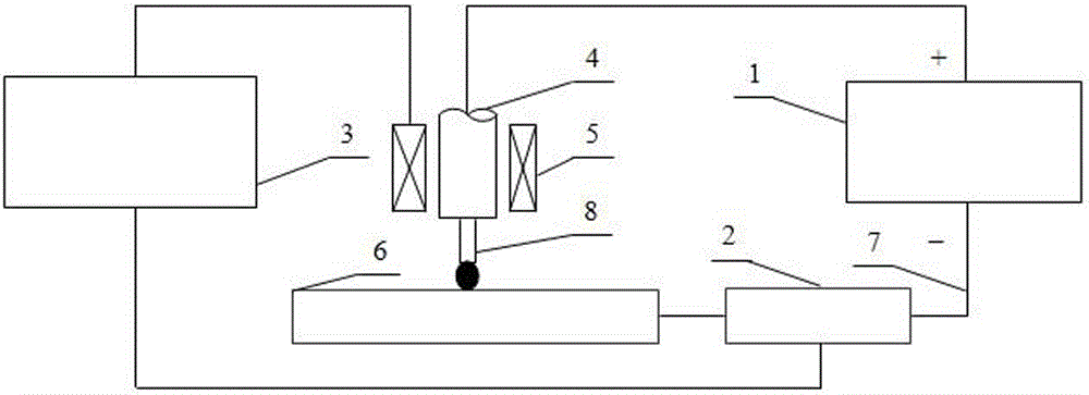
[0019] Short-circuit transition CO under synchronous magnetic field control 2 The composition of the welding system specifically includes: CO 2 Inverter welding power supply 1, Hall sensor 2, synchronous magnetic field generator 3, CO 2 Welding torch 4, excitation coil 5, workpiece 6, welding cable 7 and welding wire 8. One of them is used for short circuit transition CO 2 The devices for welding synchronous magnetic field control include: CO 2 Composed of an inverter welding power source 1, a synchronous magnetic field generator 3 and an excitation coil 5. It is characterized in that: CO 2 The inverter welding power supply 1 can output the preset welding current waveform and arc voltage waveform which are consistent with the welding current waveform and arc voltage waveform controlled by ordinary waveforms but have a higher frequency; the synchronous magnetic field generator 3 has the excitation current magnitude, magnetic field frequency and excitation coil Temperature ...


PUM


Abstract

The invention relates to a device and method for synchronous magnetic field control of short-circuit transition CO2 welding, which belongs to the technical field of welding electromagnetic control, and particularly relates to a welding method for controlling short-circuit arc droplet transition form by applying a longitudinal synchronous magnetic field. It is characterized in that: a synchronous magnetic field control idea is proposed, that is, by including the arc droplet formation section, droplet short circuit and liquid bridge formation section, necking and energy reduction section in the short circuit transition CO2 welding droplet transfer process Different types of magnetic pulses are applied at different stages to meet the needs of different current magnitudes and electromagnetic forces in different stages of short-circuit transition, especially at low and medium currents. On the basis of waveform control, synchronous magnetic field control can be applied to promote The smooth and rapid transition of molten droplets achieves the goals of reducing spatter and improving forming.

Description

technical field [0001] The invention belongs to the technical field of welding electromagnetic control, and in particular relates to a welding method in which an external longitudinal synchronous magnetic field is applied to control the transition form and transition process of short-circuit arc droplet. Background technique [0002] CO 2 Since the advent of gas shielded welding in the 1950s, it has attracted much attention for its low cost, high efficiency and energy saving, simple operation and easy automation. But CO 2 Because the droplet transfer form is mostly short-circuit transfer, there are two major disadvantages in the welding process: large spatter and poor weld formation. This not only caused the waste of a large amount of welding wire melting but a low deposition rate, but also caused a lot of spattering and heavy follow-up slag removal work, which brought great inconvenience to actual production. Moreover, these two disadvantages also limit the short-circuit...

Claims


Application Information

Patent Timeline
Patent Type & Authority Patents(China)
IPC IPC(8): B23K9/08B23K9/16
CPCB23K9/08B23K9/16
Inventor 常云龙路林梅强
Owner SHENYANG POLYTECHNIC UNIV
Learn More