
Induction heating positioning device

A positioning device and induction heating technology, applied in induction heating and other directions, can solve problems such as affecting molding quality, high labor intensity of operators, affecting heating quality, etc., and achieve the effect of ensuring quality consistency, low production cost, and reducing labor intensity.

Inactive Publication Date: 2015-03-25
GUIZHOU HANGRUI AVIATION PRECISION PARTS MFG
View PDF2 Cites 1 Cited by
  • Summary
  • Abstract
  • Description
  • Claims
  • Application Information

AI Technical Summary

Problems solved by technology

[0005] (1) The labor intensity of the operator is high, and it is not difficult to heat several or dozens of blanks. It is very difficult to continuously heat thousands of blanks. At the same time, more than three pliers or tweezers must be prepared, because the pliers or tweezers are metal. Under the dual effects of heat conduction and acute skin effect, several pieces of blanks will become hot when continuously heated, and cannot be handled with bare hands, and it is inconvenient to operate with gloves. Only continuous replacement of tools is required;
[0006] (2) The positioning is not accurate, which affects the heating quality, which in turn affects the molding quality
In order to ensure the consistency of the heating of the billet, the billet needs to be placed in the center of the induction coil. Human operation, no matter how high the technology is, it is difficult to guarantee; once a quartz tube with an appropriate wall thickness was placed in the induction heating tube, when the billet was placed in the quartz tube , the blank is basically in the center of the induction coil, but the blank for manufacturing fasteners is usually only a dozen grams. After the power is turned on, the instantaneous magnetic field pushes the blank out of the induction coil
[0007] (3) There are potential safety hazards; during operation, pliers or tweezers will inevitably touch the induction coil, resulting in accidents that endanger personal safety

Method used


Image

  • Induction heating positioning device

Examples


Embodiment Construction

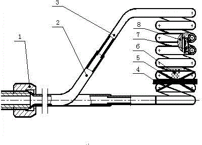
[0020] An induction heating positioning device according to the present invention, its structure mainly includes: sealing nut 1, support arm 2, induction coil 3, asbestos board 4, asbestos rope 5, adjustment block 6, quartz tube 7, blank 8, In the induction heating device of the present invention, the bending extension at the upper end of the induction coil 3 is connected to the support arm 2, and the other end of the support arm 2 is connected to the induction heating device through the sealing nut 1. The axial direction of the induction coil 3 is vertical, and at the lower end of the induction coil 3 Pad an asbestos board 4 or a non-metallic material that can withstand 1200°C, bind it with an asbestos rope 5, put the quartz tube 7 into the heating tube, and when heating the blank 8, select an appropriate adjustment block 6 according to the length of the blank 8 to It is advisable that blank 8 can be conveniently held with tweezers after putting into blank 8 . The outer diame...


PUM

PropertyMeasurementUnit
Outer diameteraaaaaaaaaa

Abstract

An induction heating positioning device mainly structurally comprises a sealing nut, a supporting arm, an induction coil, an asbestos board, an asbestos rope, an adjusting cushion block, a quartz tube and a blank, a curved extension portion of the upper end of the induction coil is connected with the supporting arm, the other end of the supporting arm is connected with the sealing nut, the induction coil is vertical in the axial direction, the asbestos board is arranged at the lower end of the induction coil in a cushioning mode and tied through the asbestos rope, the quartz tube is placed in a heating tube, and when the blank is heated, the appropriate adjusting cushion block is selected according to the length of the blank so that the blank can be conveniently clamped through tweezers after the blank is placed in. The induction heating positioning device is simple to manufacture and low in manufacturing cost; positioning is accurate and reliable, and consistency of product quality is guaranteed; heated blanks are wide in length range and can be as short as 3 mm and as long as 100 mm; the labor intensity of operators is relieved, and production efficiency is improved. Personal safety of the operators is guaranteed.

Description

technical field [0001] The invention relates to an induction heating device, which is mainly aimed at the induction heating of metal materials such as superalloy, titanium alloy, stainless steel, alloy steel and non-ferrous metal. Background technique [0002] With the continuous development of science and technology in our country, fasteners of special materials such as high-temperature alloys, titanium alloys, and precipitation-hardened stainless steels have been widely used in aviation, aerospace, space, ships, and other fields. From spacecraft, military and civilian satellites, rockets, missiles, military and civilian aircraft to military and civilian ships, aircraft carriers, all kinds of fasteners are required. There are at least a hundred types of fasteners used in a car, and tens of thousands of fasteners used in a civil aviation airliner. The demand for various medium and high-end special-shaped fasteners has doubled, increasing the batch size of fasteners, and cre...

Claims


Application Information

Patent Timeline
IPC IPC(8): H05B6/02
Inventor 胡平庞德钊
Owner GUIZHOU HANGRUI AVIATION PRECISION PARTS MFG
Learn More