
Electric adjusting power divider with filter function

A power divider and ESC technology, which is applied in the direction of waveguide devices, circuits, electrical components, etc., to achieve the effects of integrated applications, small loss, and small size

Active Publication Date: 2015-03-25
深圳锦峰信息技术有限公司
View PDF10 Cites 13 Cited by
  • Summary
  • Abstract
  • Description
  • Claims
  • Application Information

AI Technical Summary

Problems solved by technology

According to research, there is no public report on the adjustable power divider with filtering function at present. Therefore, the present invention proposes an electronically adjustable power divider with integrated band-pass filtering function.

Method used


Image

  • Electric adjusting power divider with filter function
  • Electric adjusting power divider with filter function
  • Electric adjusting power divider with filter function

Examples


Embodiment

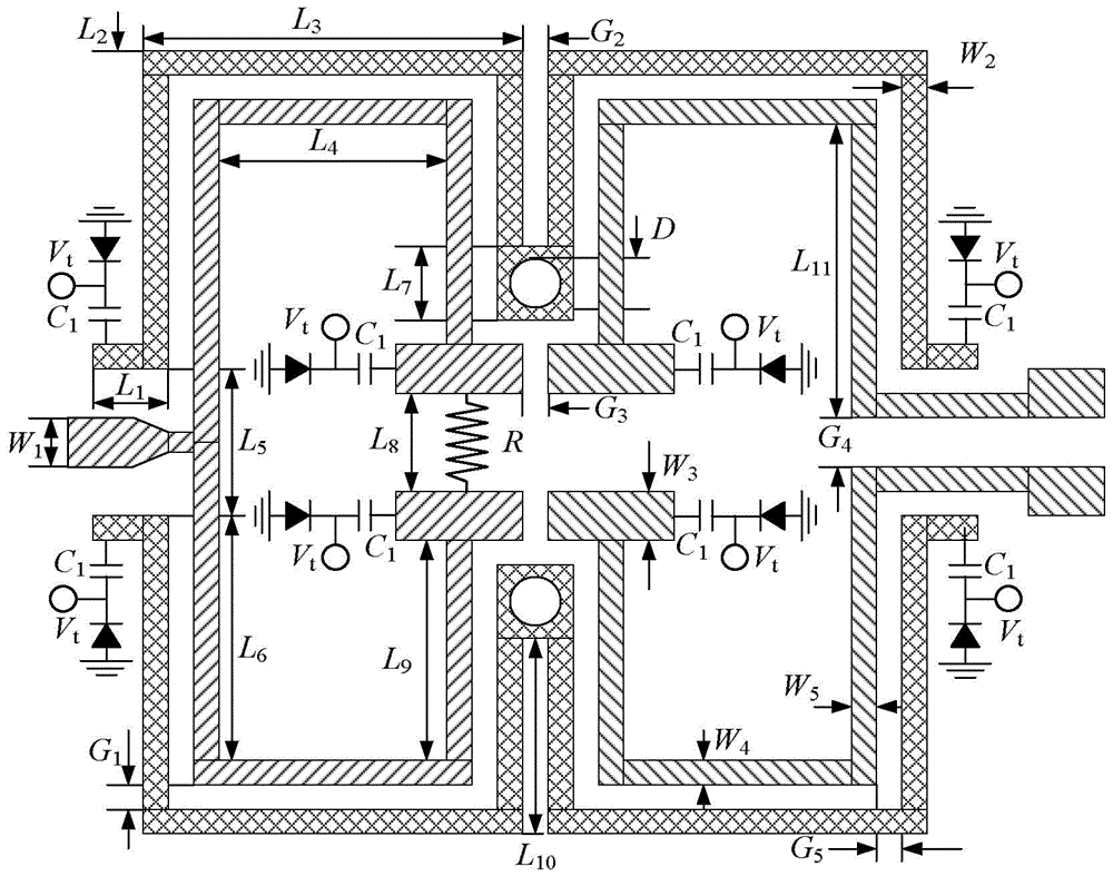
[0029] Such as figure 2 As shown in , as an example, the design of the ESC power divider with filtering function, the specific circuit size selection is as follows: W 1 =2.33mm, W 2 =0.5mm, W 3 =1.4mm, W 4 =0.5mm, W 5 =1.3mm, L 1 =2mm, L 2 =9.7mm, L 3 =12.9mm, L 4 =10.1mm, L 5 =3mm, L 6 =8.5mm, L 7 =1.2mm, L 8 =1.2mm, L 9 =6.7mm, L 10 =7mm, L 11 =9.4mm, G 1 =0.2mm, G 2 =0.3mm, G 3 =0.15mm, G 4 =1.2mm, G 5 =0.3mm, D =0.8mm, R =150Ω, C 1 =2pF; Toshiba's 1sv277 is the varactor diode selected in this design. The overall size is 34mm×23.6mm.

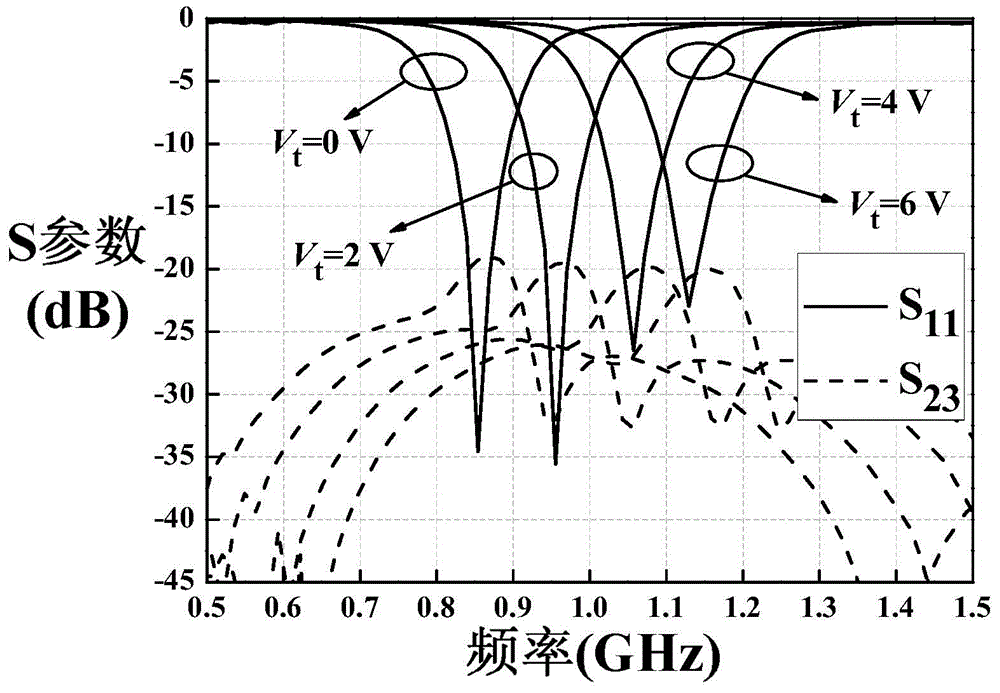
[0030] Such as image 3 Shown as S 11 and S 23 The actual measurement results show that the return loss is greater than 20dB and the isolation is better than 18dB.

[0031] Such as Figure 4 Shown as S 22 and S 33 The measured results are better than 15dB in any case, achieving a very good match.

[0032] Such as Figure 5 Shown as S 21 and S 31 According to the actual measurement resul...


PUM


Abstract

The invention provides an electric adjusting power divider with a filter function. The entire circuit structure of the electric adjusting power divider is symmetric, and the power dividing ratio is 1:1. Two pairs of quarter-wave resonators which are coupled with each other form two filter networks, and the characteristic of band-pass filtering is achieved. The matching of three ports of a circuit and the isolating of two output ports of the circuit are achieved by resistors. According to an on-load variable capacitance diode, the electrical length of the resonators and the electrical length of a feeder line are adjusted by changing the on-load voltage of the on-load variable capacitance diode, and the purpose that the center frequency is adjustable is achieved. In addition, three transmission zeros are introduced by source load coupling, so that the electric adjusting power divider has high selectivity and is also good in stopband suppression effect.

Description

technical field [0001] The invention relates to an electronically adjustable power divider with a filtering function, in particular to an electronically adjustable equal-division power divider integrated with a band-pass filter function that can be applied to a radio frequency front-end circuit. Background technique [0002] In mobile communication, satellite communication, wireless sensor network nodes and wearable wireless devices, it is necessary to reduce the size of the device or accommodate more functional modules in a limited space, so miniaturization is an inevitable trend of development. Since the volume of the RF front-end occupies a large part of the wireless equipment, it is of great theoretical significance and application value to carry out in-depth research on its miniaturization. [0003] In the past, research on the miniaturization of radio frequency devices focused on the performance improvement and miniaturization of individual components. After several y...

Claims


Application Information

Patent Timeline
Patent Type & Authority Applications(China)
IPC IPC(8): H01P5/16H01P1/203
Inventor 赵小兰徐金旭高立章秀银
Owner 深圳锦峰信息技术有限公司
Learn More