Hospital infection equipment remote monitoring management system and method
A technology of remote monitoring and management system, which is applied in the field of remote monitoring and management system of hospital-sensing equipment, can solve problems such as reducing monitoring efficiency, increasing monitoring time, and consuming enterprise resource costs.
- Summary
- Abstract
- Description
- Claims
- Application Information
AI Technical Summary
Problems solved by technology
Method used
Image
Examples
Embodiment 1
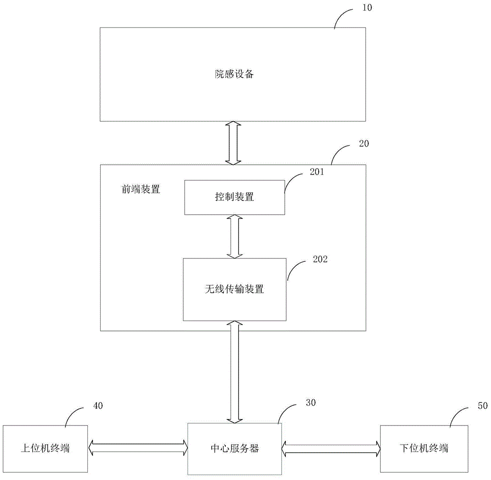
[0021] refer to figure 1 , figure 1 It is a structural block diagram of the remote monitoring and management system for hospital sensory equipment provided by the embodiment of the present invention.
[0022] The remote monitoring and management system of the hospital sense equipment includes the hospital sense device 10, and also includes:
[0023] The front-end device 20 is connected with the sensory device 10, and is used to receive the sensory device control instruction from the central server 30, control the sensory device 10 according to the device control command, and obtain the sensory device The operation data of the hospital sense equipment and the data of the work completion of the hospital sense equipment fed back by the equipment, and the operation data of the hospital sense equipment and the data of the work completion of the hospital sense equipment are uploaded;
[0024] The central server 30 is connected to the front-end device 20, and is used to send the co...
Embodiment 2
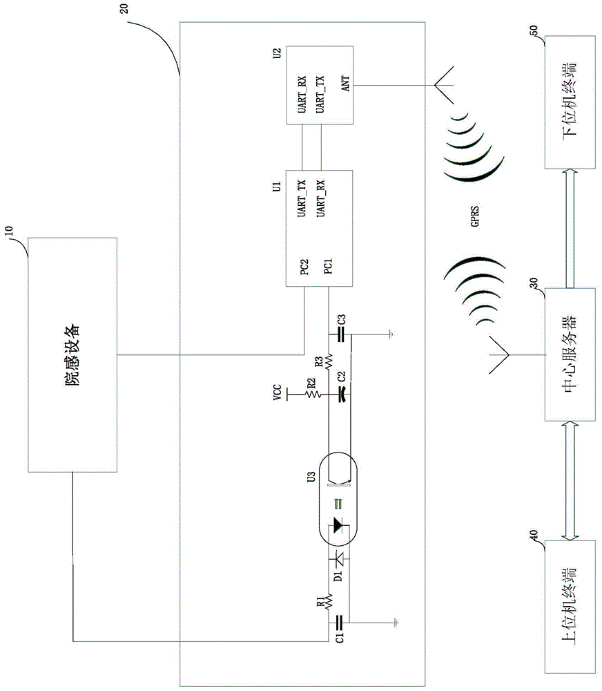
[0031] refer to figure 2 , figure 2 It is a circuit diagram of the interconnection between the front-end device 20, the central server 30, the upper computer terminal 40 and the lower computer terminal 50 in the remote monitoring and management system of the hospital sense equipment provided by the embodiment of the present invention. Example related parts.
[0032] The control device 201 includes a resistor R1, a resistor R2, a resistor R3, a capacitor C1, an electrolytic capacitor C2, a capacitor C3, a diode D1, a photocoupler U3, a control chip U1, and a power supply VCC;
[0033] The first end of the resistor R1 and the first end of the capacitor C1 are commonly connected to form an input end of the control device 201;
[0034] The second end of the resistor R1 is respectively connected to the first end of the diode D1 and the anode of the photodiode in the photocoupler U3, the second end of the diode L1, the cathode of the photodiode and the capacitor The second term...
Embodiment 3
[0039] refer to figure 2, the embodiment of the present invention mainly describes the asynchronous receiving end, the asynchronous sending end, the wireless data sending end and the wireless data receiving end of the wireless transmission device 202 provided in the front-end device 20, and the details are as follows:
[0040] The wireless transmission device 202 adopts a wireless data transceiver U2;
[0041] The asynchronous receiving terminal UART_RX and the asynchronous transmitting terminal UART_TX of the wireless data transceiver U2 are the asynchronous receiving terminal and the asynchronous transmitting terminal of the wireless transmission device 202, and the ANT terminal of the wireless data transceiver U2 is the radio frequency of the front-end device 20 Input and output terminals, that is, wireless data receiving and transmitting terminals.
[0042] Among them, through the wireless data transceiver U2, the front-end device 20 uploads the operation data of the hos...
PUM
 Abstract
Description
Claims
Application Information
 - R&D
- Intellectual Property
- Life Sciences
- Materials
- Tech Scout
- Unparalleled Data Quality
- Higher Quality Content
- 60% Fewer Hallucinations
Browse by: Latest US Patents, China's latest patents, Technical Efficacy Thesaurus, Application Domain, Technology Topic, Popular Technical Reports.
© 2025 PatSnap. All rights reserved.Legal|Privacy policy|Modern Slavery Act Transparency Statement|Sitemap|About US| Contact US: help@patsnap.com


