Ultrasonic flow meter

A flowmeter and ultrasonic technology, applied in the field of ultrasonic flowmeters, can solve problems such as disturbing the propagation of sound wave signals and reducing the accuracy of measuring liquid flow.

Active Publication Date: 2015-03-25
SMC CORP
View PDF6 Cites 6 Cited by
  • Summary
  • Abstract
  • Description
  • Claims
  • Application Information

AI Technical Summary

Problems solved by technology

Due to the adhesion of the air bubbles, the air bubbles interfere with the propagation of the acoustic signal, resulting in a decrease in the accuracy of the measured liquid flow

Method used


Image

  • Ultrasonic flow meter
  • Ultrasonic flow meter
  • Ultrasonic flow meter

Examples


Embodiment Construction

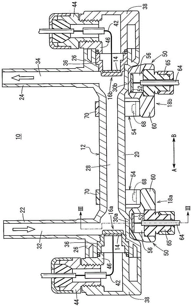
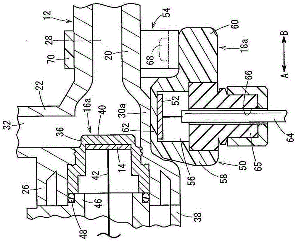
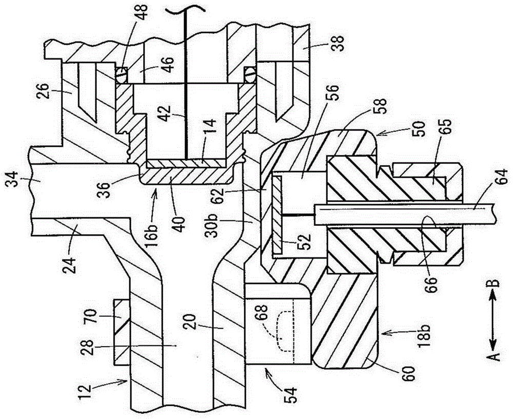
[0015] Such as figure 1 As shown, an ultrasonic flowmeter 10 according to an embodiment of the present invention includes: a housing (housing) 12 having a passage 28 to which fluid such as water, chemical solution, etc. is supplied; a pair of detection units 16a, 16b, The detection unit is arranged on the opposite end of the casing 12, and is installed therein an acoustic wave transmitting and receiving unit 14 for transmitting and receiving acoustic waves; and a pair of vibration generating mechanisms 18a, 18b, which are provided on the detecting unit. The position on the outer peripheral side of l6a, l6b.

[0016] The housing 12 includes: a piping 20 formed in a straight line of, for example, a metallic material such as stainless steel; a supply portion (port) 22 connected substantially perpendicularly to one end of the piping 20; and a discharge portion (port) 24 , the discharge portion is connected substantially perpendicular to the other end of the pipeline 20 . The sup...


PUM


Abstract

An ultrasonic flow meter (10) is equipped with a housing (12) through which a liquid flows, and a pair of detection units (16a, 16b) disposed on opposite ends of the housing (12) and including acoustic wave transmitting and receiving units (14) capable of transmitting and receiving acoustic wave signals. Vibration generating mechanisms (18a, 18b) having vibration generating bodies (52) arranged perpendicularly to the detection units (16a, 16b) are disposed on an outer circumferential side of the housing (12). In addition, when the flow rate of the liquid that flows through the housing (12) is measured, the vibration generating bodies (52) are energized and made to vibrate, such that gas bubbles, which adhere to cover members (36) in contact with the liquid and that cover the acoustic wave transmitting and receiving units (14), are removed by the vibrations.

Description

technical field [0001] The present invention relates to an ultrasonic flowmeter for detecting the flow rate of a liquid based on a difference in propagation speed when sound waves are transmitted through the liquid. Background technique [0002] Heretofore, for example, there are known ultrasonic flowmeters in which a pair of sensors are respectively arranged on the upstream side and the downstream side of a pipeline through which a liquid flows. Ultrasonic waves transmitted from one of the sensors are reflected by the inner wall surface of the pipe and received by the other sensor, and the flow rate or flow rate of the liquid is measured based on the difference in the propagation speed of the ultrasonic waves. [0003] In such an ultrasonic flowmeter, for example, Japanese Patent No. 2793133 (Patent Document 1) discloses that a measurement line is provided with a supply pipe and a discharge pipe to which liquid is supplied and from which liquid is discharged. was discharge...

Claims


Application Information

Patent Timeline
Patent Type & Authority Applications(China)
IPC IPC(8): G01F1/66
CPCG01F1/662G01F1/667G01F1/66
Inventor 铃木贵光永田章纪
Owner SMC CORP
Why Eureka
Try Eureka