Sealing Mechanism And Sealing Method

A sealing mechanism and sealing technology, applied in chemical instruments and methods, separation methods, engine sealing, etc., can solve problems such as processing tolerances, and achieve the effect of reducing installation burden

Active Publication Date: 2015-03-25
DIONEX SOFTRON
View PDF8 Cites 2 Cited by
  • Summary
  • Abstract
  • Description
  • Claims
  • Application Information

AI Technical Summary

Problems solved by technology

At the same time, the filter or mixer within the system must also be sealed so that no medium can bypass it, but only flow through it
Additionally, filters or mixers used in HPLC techniques often have machining tolerances to consider when sealing

Method used


Image

  • Sealing Mechanism And Sealing Method
  • Sealing Mechanism And Sealing Method
  • Sealing Mechanism And Sealing Method

Examples


Embodiment Construction

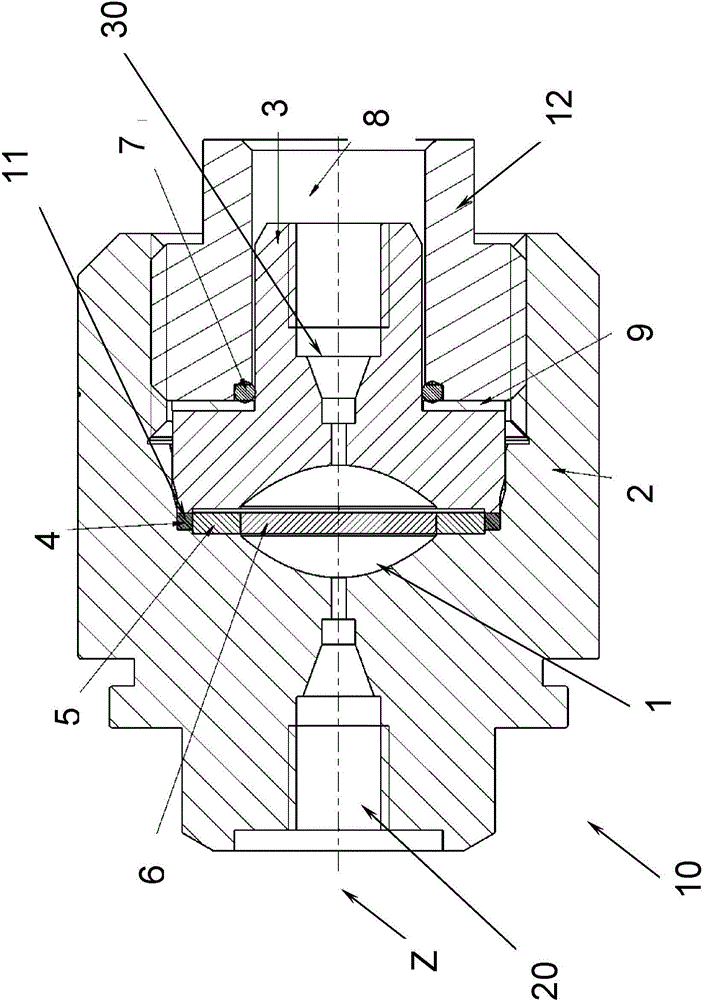
[0022] figure 1 A connection from HPLC technology is shown, which allows the accommodation of a replaceable frit 6 and is designed for working pressures above 100 MPa. The illustrated sealing device 10 comprises a housing 2 which is substantially rotationally symmetrical about the Z-axis. The pressing member 3 can enter the housing through the open end of the housing 2 along the Z axis. The screw-in part 12, which applies force to the pressing part 3 from the rear side, can be screwed into the housing 2 along the Z direction for this purpose, whereby the pressing part 3 can be inserted into the housing 2 (in the figure 1 from right to left) or firmly clamped in it. The housing 2 or the pressing part 3 has communicating channels 20 or 30 , from which a medium can be introduced under high pressure into the interior 1 formed by the housing 2 or the pressing part 3 or can be discharged. The medium is now guided through the disk-shaped frit 6 arranged coaxially to the Z-axis in ...


PUM


Abstract

The invention relates to a sealing mechanism and to a method which forms the basis for the former and in which a clamping ring which loads a sealing element compensates for an operationally induced change in the volume which is available for the sealing element, as a result of which the sealing action of the sealing element can be maintained reliably even in the case of high operating pressures.

Description

technical field [0001] The invention relates to a sealing mechanism and a sealing method for sealing an inner cavity to which a high internal pressure can be applied. Background technique [0002] Especially in HPLC methods (high performance liquid chromatography), which work with very high pressures, stringent requirements are placed on sealing. This is the case, for example, with pumps, where pressures of more than 100 MPa occur. Although attempts have been made in the prior art to support a good seal with as small a manufacturing tolerance as possible, the high pressures that occur have resulted in no satisfactory solution to date. Embodiments are known in which the annular seal is prestressed in the axial direction to achieve the desired sealing action. However, the increased internal pressure that occurs during operation causes the relatively sealed parts to be forced apart, thereby also reducing the pre-tensioning pressure introduced into the seal and thus impairing ...

Claims


Application Information

Patent Timeline
IPC IPC(8): F16J15/00
CPCB01D15/10F16J15/021F16J15/028G01N30/6026
Inventor R·施罗德尔M·沃纳
Owner DIONEX SOFTRON
Why Eureka
Try Eureka