Eyelet

A technology for corns and eye buttons, applied in the field of eyelets, can solve the problems of inferior use, falling off of eyelets, not fully eliminating fabric breakage, etc., to achieve the effects of weight reduction, installation burden reduction, and product unit price reduction.

Inactive Publication Date: 2012-05-23
YKK CORP
View PDF6 Cites 0 Cited by
  • Summary
  • Abstract
  • Description
  • Claims
  • Application Information

AI Technical Summary

Problems solved by technology

[0008] However, in any of the above-mentioned conventional single-member eyelets, all eyelets are only between the flange and the flange abutting portion opposite to the flange or between the inner surface of the flange and the portion opposite to the flange. The structure of the material part around the mounting hole is pressed between the flange abutting parts, so from the point of view of the mounting strength to the material, it is not as good as the two-member type eyelet using the washer, or it is still not enough to eliminate the riveting. Or the cloth breaks during use, and in the case of thinner materials, the eyelets fall out of the mounting holes due to the stretching of the material

Method used


Image

  • Eyelet
  • Eyelet
  • Eyelet

Examples


Embodiment Construction

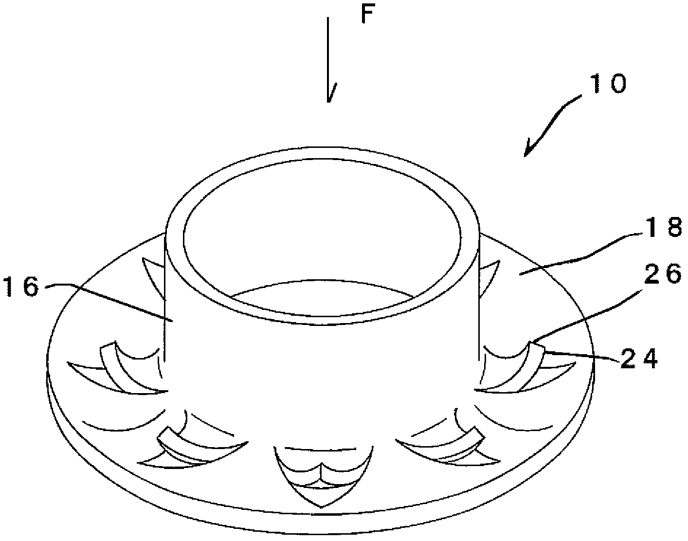
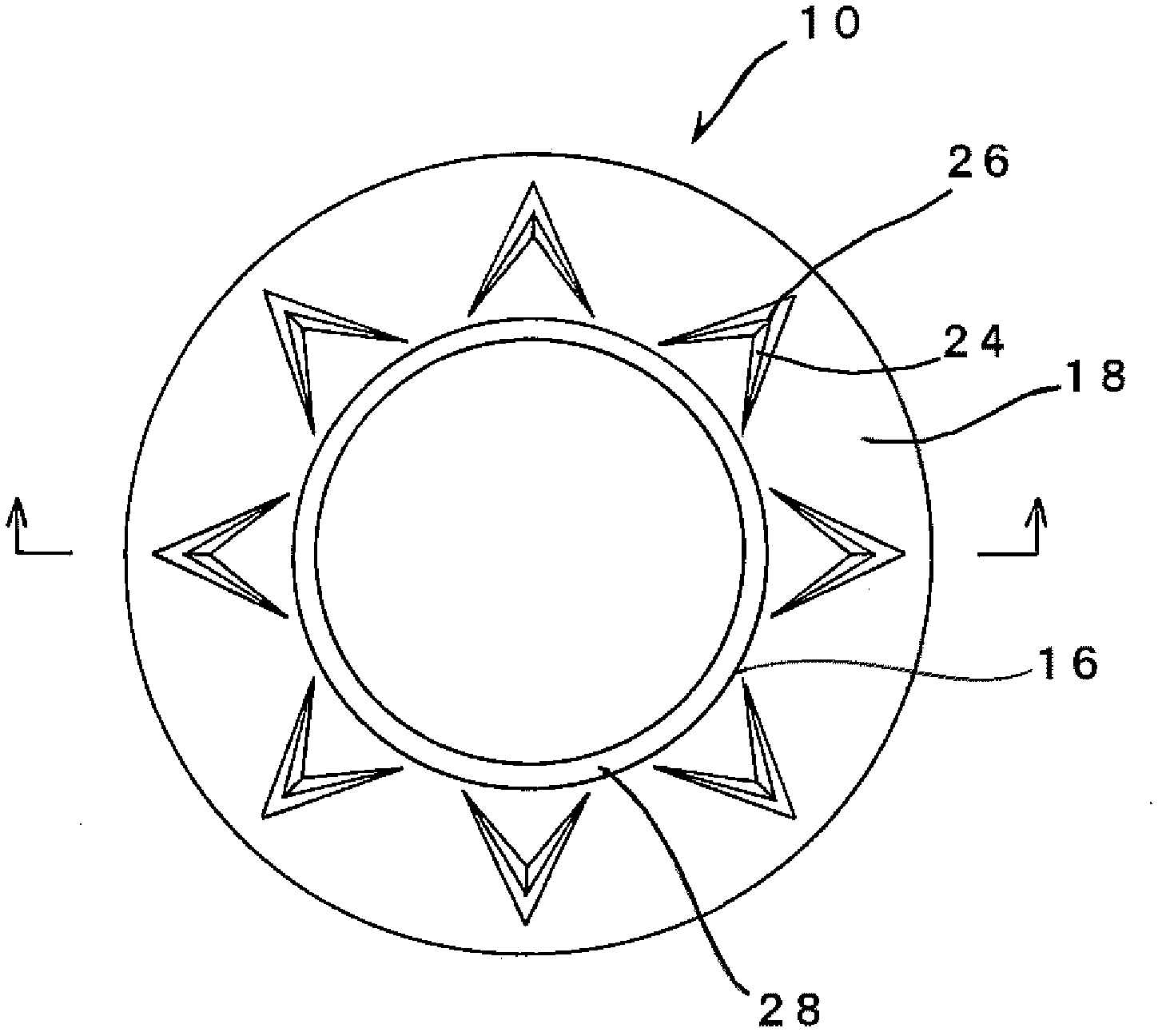
[0034] Below, refer to Figure 1 to Figure 5 The one-piece type eyelet of the present invention will be described in detail.

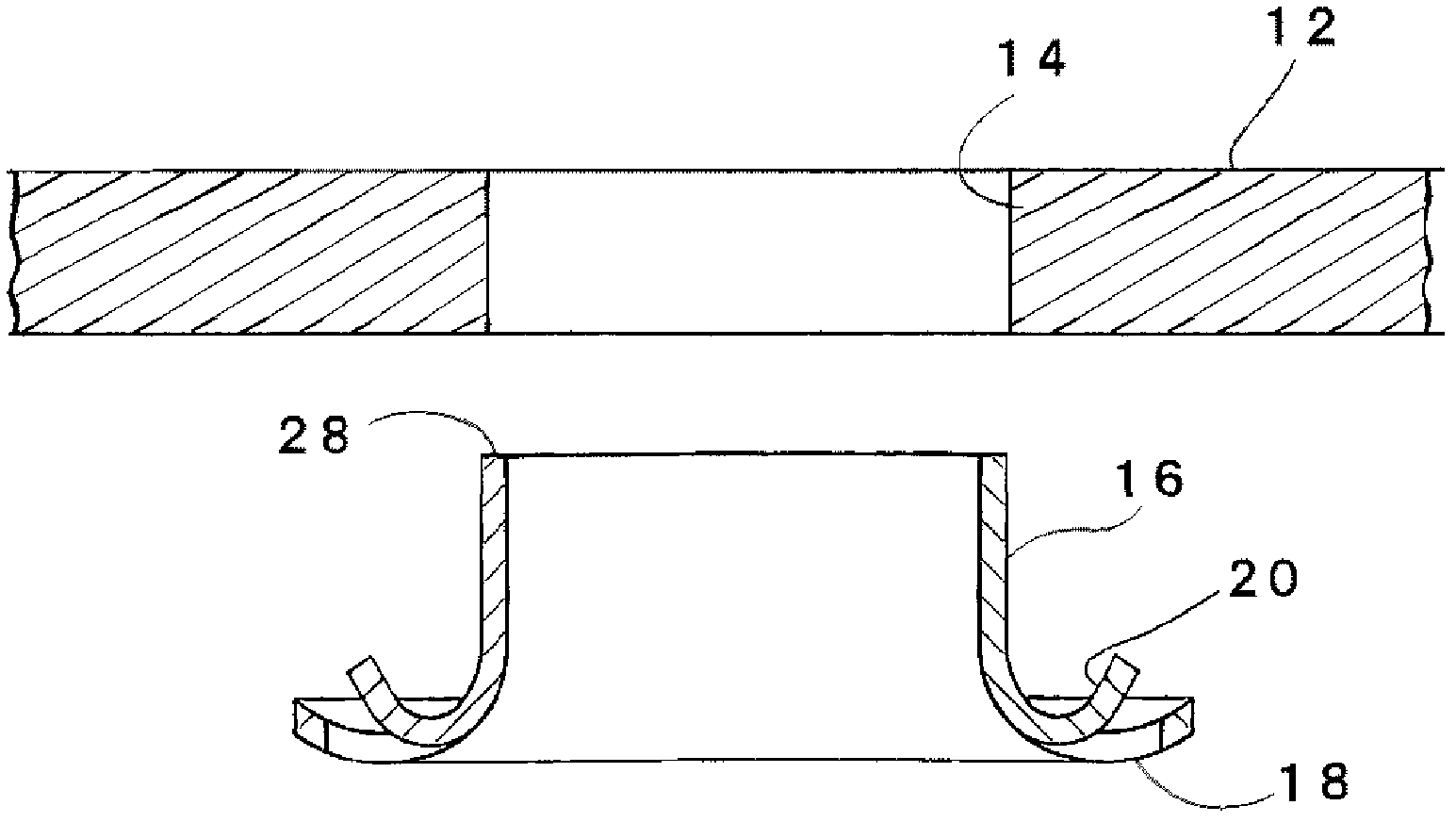
[0035] figure 1 It is a perspective view showing the eyelet 10 of the one-piece eyelet of the present invention before the riveting process. The eyelet 10 is made of representative metals such as brass, iron, nickel, aluminum, etc., and the eyelet 10 has a hollow cylindrical column 16 and a flange 18, and the column 16 has a structure capable of being inserted into a penetratingly formed surface. Materials such as cloth, resin sheet, etc. 12 ( image 3 ) on the outer diameter of the mounting hole 14, the flange 18 is configured on the material portion around the mounting hole 14, in image 3 In the embodiment, the flange 18 extends radially outward from the lower end of the column 16 in a state continuous with the column 16 .

[0036] After making the column 16 pass through the mounting hole 14, it becomes as riveted as Figure 4 and Figure 5 W...


PUM


Abstract

An eyelet which can be mounted to a material by strength equivalent to or higher than strength obtained by a two-member type eyelet using a washer and which does not come out of a mounting hole when the eyelet is staked, when cloth breaks during use, or when the cloth stretches and contracts. A material (12) is pressed between the tips (26) of claws (24) and the inner surface (32) of a flange engaging section (30), where the claws (24) are formed by cutting and raising portions of a flange (18) toward the material. The construction allows an eyelet to be secured with sufficient strength without causing pressing force to be concentrated to one portion of the material and prevents an edge (28) of the flange engaging section (30) from acting as a cutting edge which cuts cloth. The cloth is pressed at a position different from positions at which the cloth is pressed by both the edge (28) of the flange engaging section (30) and an edge (34) of the flange (18).

Description

technical field [0001] The present invention relates to an eyelet which is riveted and fixedly mounted on a mounting hole formed in clothing fabrics and other materials, and in particular relates to an eyelet which is fixedly mounted on a mounting hole without using a gasket member. Background technique [0002] Conventionally, eyelets are used as the main form of eyelets to perform riveting processing on mounting holes formed in advance on materials such as clothing fabrics, covering sheets, and shoes, and to clamp the material parts. There are two-piece eyelets that combine eyelets and washers, and one-piece eyelets that don’t use washers. In the double-member type eyelet, the eyelet has a post that passes through the mounting hole and a flange that extends radially outward from the end edge of the post and is formed when it is fixed in the mounting hole of the material When installing the eyelet, first, after passing the post of the eyelet through the mounting hole and t...

Claims


Application Information

Patent Timeline
Patent Type & Authority Applications(China)
IPC IPC(8): A44B1/24A44B13/00A44B21/00
CPCA44B13/0082Y10T24/3742
Inventor 长谷川建二
Owner YKK CORP
Why Eureka
Try Eureka