
Pipe coiler

A tube-winding and tube-feeding technology, which is applied in the direction of thin material processing, delivery of filamentous materials, transportation and packaging, etc., can solve the problems of difficulty in ensuring the uniformity of the helical distance of the heat exchange tube, affecting the heat exchange effect, and low work efficiency , to achieve the effect of reducing the risk of scrapping, saving labor costs, and smooth pipe delivery

Active Publication Date: 2015-03-25
ZHENHAI PETROCHEM JIANAN ENG
View PDF8 Cites 8 Cited by
  • Summary
  • Abstract
  • Description
  • Claims
  • Application Information

AI Technical Summary

Problems solved by technology

[0004] Due to the influence of human factors, it is difficult to ensure the uniformity of the helical distance of the heat exchange tubes installed, which affects the heat exchange effect to a certain extent.
At the same time, in the prior art, because the coiled tube bundles are stacked on the ground or placed on the I-shaped wheel, and pulled out manually, the labor intensity is high and the work efficiency is low, and because the remaining coiled tube bundles will automatically fluff up after the coiled tubes are pulled out , after the fluffy tube bundle overlaps or knots, it is difficult to get out of the tube, and pulling out the tube forcibly will damage the heat exchange tube

Method used


Image

  • Pipe coiler
  • Pipe coiler
  • Pipe coiler

Examples


Embodiment Construction

[0045] The present invention will be further described in detail below in conjunction with the accompanying drawings and embodiments.

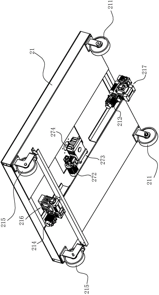
[0046] Such as Figure 1 to Figure 13 As shown, the pipe winding machine includes a pipe unwinding device 2, a pipe feeding device 1, sensors and a control system.

[0047] Wherein, pipe delivery device 1 comprises:

[0048] The tube delivery base 11 is provided with a wheel 111 on the lower surface of the tube delivery base, and the tube delivery base 11 is provided with a guide mechanism 12 . The guide mechanism 12 in this embodiment includes a connecting plate 121 arranged on the pipe feeding base 11, two fixed pulleys 122 are arranged in parallel on the connecting plate 121, and the guide rod arranged on the pipe winding operation platform passes through the two fixed pulleys. between the pulleys.

[0049] In this way, under the cooperation and limiting action of the guide rod 4 and the fixed pulley, the tube delivery base 11 walks alon...


PUM


Abstract

The invention relates to a pipe coiler. The pipe coiler comprises a riding wheel used for bearing a pipe to be coiled and is characterized by further comprising a pipe conveying device and a pipe uncoiling device, wherein the pipe conveying device sequentially comprises a pipe conveying base, a lifting mechanism, a fine adjustment mechanism, a supporting base, a radial adjusting mechanism and a riding wheel from bottom to top, the pipe uncoiling device comprises a pipe uncoiling base, a base plate is arranged on the pipe uncoiling base and provided with a support, and the support is provided with a rotating disk which is provided with an axial clamping mechanism, a radial clamping mechanism, a telescopic sleeve, an anti-shrinking mechanism, sensors and a control system. Through the pipe coiler, the pipe feeding position can be tracked in real time, the pipe conveying height, the pipe conveying angle and the pipe conveying speed can be adjusted in real time, the pipe coiling quality is guaranteed, the scrap risk is reduced, the labor intensity of workers is relieved, and manual cost is saved; due to the design of the pipe uncoiling device, it is effectively prevented that in the pipe distributing process, a coiled pipe bundle loosens, the loosened pipe bundle overlaps and is knotted, the pipe can go out smoothly, pipe distribution quality is guaranteed, and product quality is good.

Description

technical field [0001] The invention relates to a pipe winding machine. Background technique [0002] The heat exchange tubes are spirally wound in the shell, which is one of the shell and tube heat exchanger structures. These heat exchange tubes are arranged in layers and coiled coaxially on the core. In order to facilitate the positioning of the heat exchange tubes of each layer, a spacer is provided between adjacent layers, the spacer is parallel to the axis of the core body, and a plurality of slots for positioning the heat exchange tubes are arranged at intervals on the spacer. [0003] Since the winding quality of each heat exchange tube will directly affect the heat transfer performance of the heat exchanger, the rationality of the design of the tube winding machine is particularly important. However, the existing pipe winding machines generally include a motor and support seats for supporting the two ends of the core body. The motor drives the core body to rotate th...

Claims


Application Information

Patent Timeline
Patent Type & Authority Applications(China)
IPC IPC(8): B65H49/18B65H51/00B65H81/00
Inventor 张贤安赖德海赵洪勇李晓红周继平王一刚范胜利蔡枫张伟大忻红波梁培元
Owner ZHENHAI PETROCHEM JIANAN ENG
Learn More