Eureka AIR delivers breakthrough ideas for toughest innovation challenges, trusted by R&D personnel around the world.

Automatic soldering tin machine

An automatic welding and soldering technology, applied in tin feeding devices, welding equipment, auxiliary welding equipment, etc., can solve the problems of not realizing full automation, affecting product life, scalding electronic components, etc., to ensure quality and improve production efficiency. Effect

Inactive Publication Date: 2015-03-25
东莞市东润机电设备有限公司
View PDF7 Cites 21 Cited by
  • Summary
  • Abstract
  • Description
  • Claims
  • Application Information

AI Technical Summary

Problems solved by technology

[0002] At present, most of the existing soldering machines are three-axis or four-axis automatic soldering machines, which rotate through the X-axis, Y-axis, Z-axis and welding direction, and can ensure all-round work when soldering and infiltrating rosin. Dead angles cause quality problems, which in turn affect the life of the product
Because there are various electronic components of different heights on the existing products, if the soldering iron is soldered at a vertical angle, it is easy to burn the electronic components next to it, and the quality of the product cannot be guaranteed. It is necessary to separate the steps and use manual soldering. In this way, the requirement of full automation cannot be realized.

Method used


Image

  • Automatic soldering tin machine
  • Automatic soldering tin machine

Examples


Embodiment Construction

[0019] The present invention will be further described below in conjunction with the accompanying drawings and embodiments, which are preferred embodiments of the present invention.

[0020] Example.

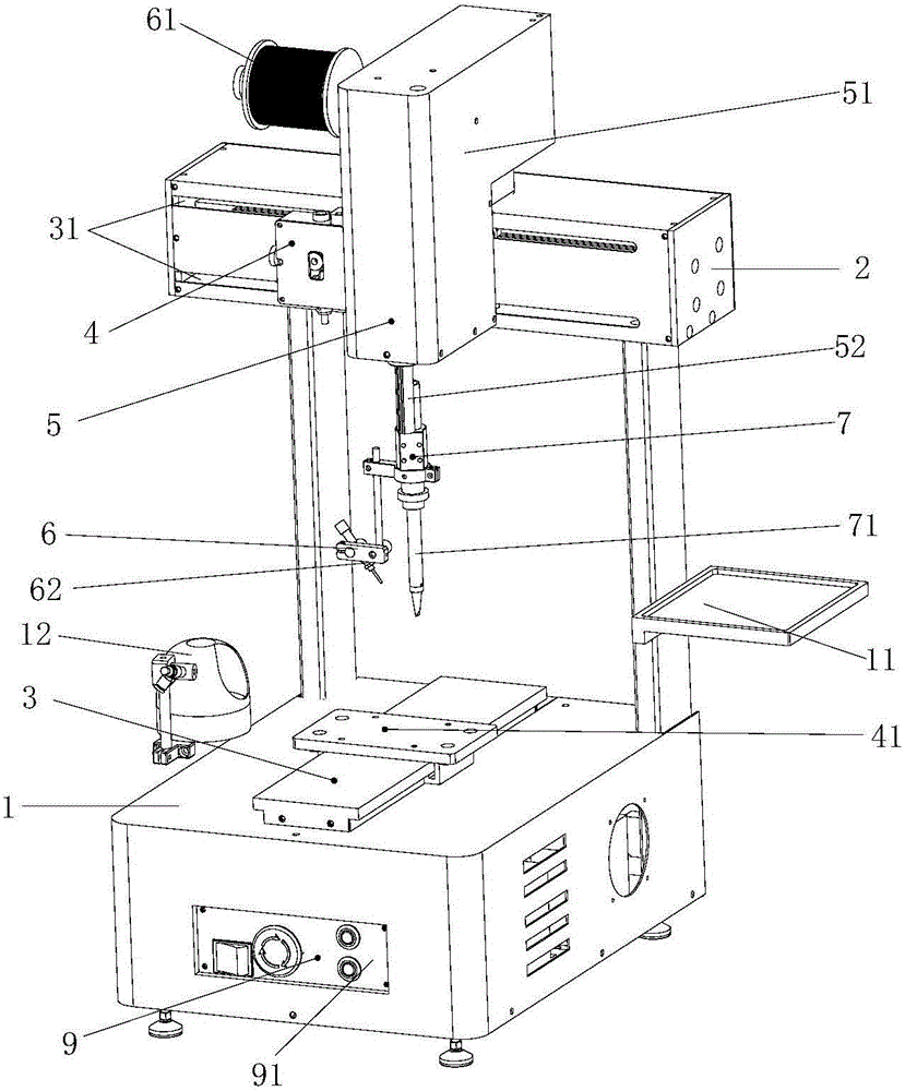
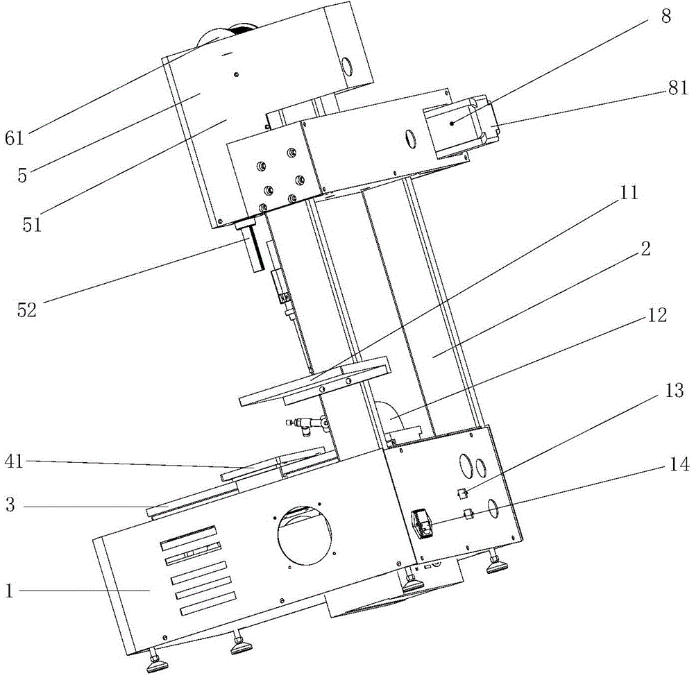
[0021] Such as figure 1 , figure 2 As shown, an automatic soldering machine of the present invention includes a base 1, and the base 1 is provided with a frame 2, an X-axis soldering mechanism 3, a Y-axis soldering mechanism 4, a Z-axis soldering mechanism 5, and an automatic tinning mechanism. bar mechanism 6, rotating mechanism 7, power mechanism 8 and control mechanism 9, the frame 2 is detachably connected to the X-axis soldering mechanism 3, and the Y-axis soldering mechanism 4 is screwed to the base 1, so The Z-axis soldering mechanism 5 is arranged on the X-axis soldering mechanism 3, and the Z-axis soldering mechanism 5 is detachably connected to the X-axis soldering mechanism 3. The automatic tin strip feeding mechanism 6 and the rotating mechanism 7 Respectively co...


PUM


Abstract

The invention relates to the technical field of machines, in particular to an automatic soldering tin machine. The automatic soldering tin machine comprises a base, and a rack, an X-axis soldering tin mechanism, a Y-axis soldering tin mechanism, a Z-axis soldering tin mechanism, an automatic tin bar feeding mechanism, a rotation mechanism, a power mechanism and a control mechanism are arranged on the base; the rack is detachably connected with the X-axis soldering tin mechanism, the Y-axis soldering tin mechanism is in screwed connection with the base, the Z-axis soldering tin mechanism is arranged on the X-axis soldering tin mechanism and detachably connected with the X-axis soldering tin mechanism, the automatic tin bar feeding mechanism and the rotation mechanism are each detachably connected with the Z-axis soldering tin mechanism, the power mechanism is electrically connected with the control mechanism, the rotation mechanism comprises a rotation head and a welding gun, and the welding gun is in screwed connection with the rotation head. The soldering tin direction and the soldering tin angle of the welding gun are adjusted through the rotation mechanism, electronic elements nearby welding points are avoided, it is guaranteed that the electronic elements nearby the welding points cannot be scalded, the production efficiency of the products is greatly improved, the product quality can be guaranteed, and the full-automatic requirement is met.

Description

technical field [0001] The invention relates to the technical field of mechanical equipment, in particular to an automatic soldering machine. Background technique [0002] At present, most of the existing soldering machines are three-axis or four-axis automatic soldering machines, which rotate through the X-axis, Y-axis, Z-axis and welding direction, and can ensure all-round work when soldering and infiltrating rosin. The dead angle causes quality problems, which in turn affects the life of the product. Because there are various electronic components of different heights on the existing products, if the soldering iron is soldered at a vertical angle, it is easy to burn the electronic components next to it, and the quality of the product cannot be guaranteed. It is necessary to separate the steps and use manual soldering. In this way, the requirement of full automation cannot be realized. Contents of the invention [0003] The present invention provides an automatic solde...

Claims


Application Information

Patent Timeline
Patent Type & Authority Applications(China)
IPC IPC(8): B23K3/00B23K3/08
CPCB23K3/00B23K3/063B23K3/08B23K37/02B23K2101/36
Inventor 何东海
Owner 东莞市东润机电设备有限公司
Why Eureka
Eureka Blog
Learn More