


Quick Research
Generate reliable direction feasibility study reports for your R&D in just a few steps.

Technical Q&A
Discover and master advanced knowledge NOW. Basics, ideas, possibilities, all at once.

Find Solutions
As an expert in R&D theories, this can generate solutions to your technical problems instantly.

Evaluate Feasibility
Analyze your overall solution with one click, know your potential R&D risks in advance.

Monitor Landscape
Get weekly tech updates, stay abreast of the latest tech innovations and key insights.
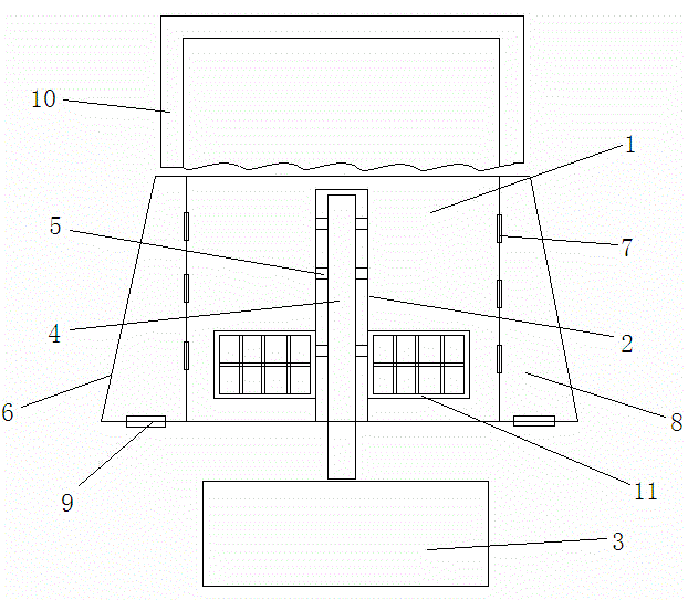
Separation treatment device for silt and water
A technology for separation and treatment of sediment, applied in the direction of centrifuges, etc., can solve the problems of more energy consumption, long time required for filtration and separation, and only suitable for small-scale use, so as to achieve good separation effect
- Summary
- Abstract
- Description
- Claims
- Application Information
AI Technical Summary
Problems solved by technology
Method used
Image

Examples
Embodiment Construction
[0035] The preferred technical solution of the present invention will be described in detail below with reference to the accompanying drawings.
[0036] Such as figure 1 As shown, a sediment and water separation processing equipment of the present invention includes an inner water bucket 1, an electric stirring rod 2 is arranged upwardly along the bottom center of the inner water bucket 1, and the electric stirring rod 2 drives the inner water bucket when rotating The water in 1 rotates, so that the sand can flow and spread in the water, avoiding deposition and it is convenient to throw the sand to the side wall. The electric stirring rod 2 is provided with a guide tube 4 that guides the water to the lower reservoir 3, and the electric stirring rod 2 are distributed with a number of water filter openings 5 communicating with the diversion tube 4, the water filter openings 5 are usually filled with filter materials or have a mesh structure with a gap smaller than sand particl...
PUM
 Abstract
Description
Claims
Application Information
 - R&D Engineer
- R&D Manager
- IP Professional
- Industry Leading Data Capabilities
- Powerful AI technology
- Patent DNA Extraction
Browse by: Latest US Patents, China's latest patents, Technical Efficacy Thesaurus, Application Domain, Technology Topic, Popular Technical Reports.
© 2024 PatSnap. All rights reserved.Legal|Privacy policy|Modern Slavery Act Transparency Statement|Sitemap|About US| Contact US: help@patsnap.com