
Cutting device and cutting method

A cutting device and wire cutting technology, applied in electrical components, semiconductor/solid-state device manufacturing, circuits, etc., can solve problems such as large offset and increased time

Active Publication Date: 2015-03-18
TOWA
View PDF11 Cites 9 Cited by
  • Summary
  • Abstract
  • Description
  • Claims
  • Application Information

AI Technical Summary

Problems solved by technology

As the size of the substrate increases, the time required to cut a substrate increases, and the offset caused by the thermal deformation of the cut object becomes a larger problem

Method used


Image

  • Cutting device and cutting method
  • Cutting device and cutting method
  • Cutting device and cutting method

Examples


Embodiment Construction

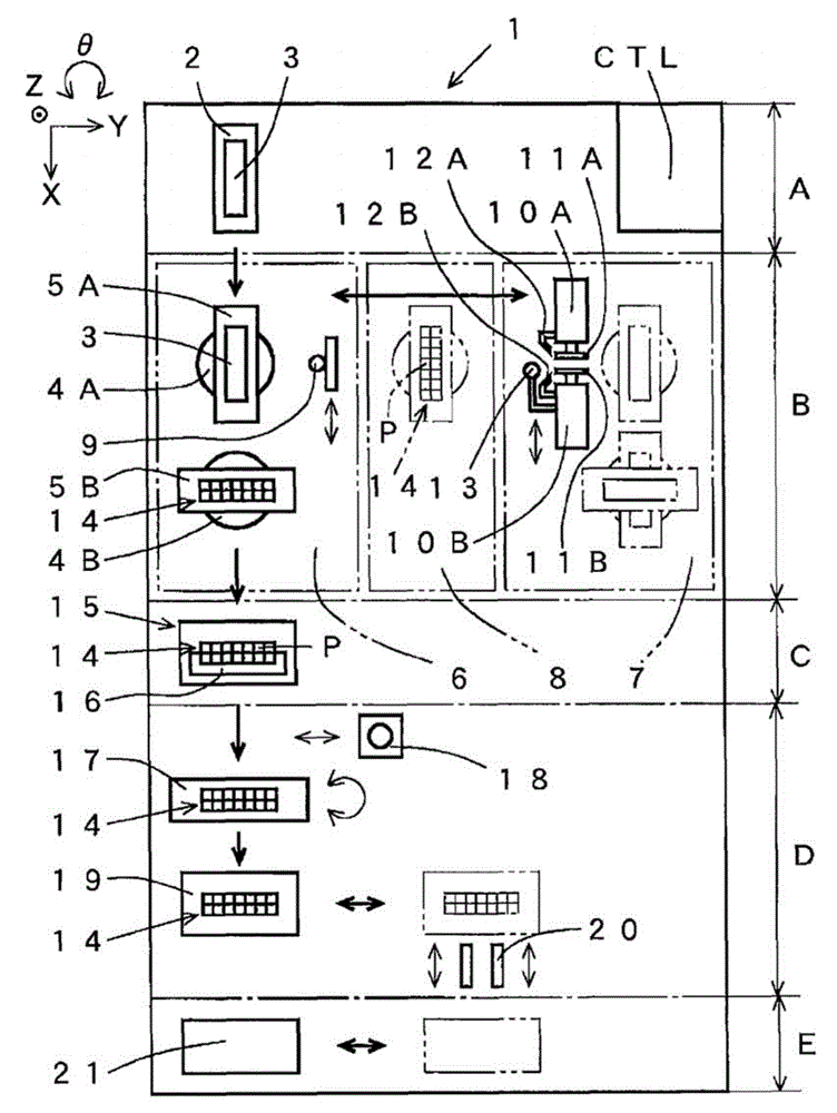
[0107] In the double-station type cutting device, the alignment mark is detected again before cutting the package substrate by using a camera for notch detection integrally provided on the spindle unit. In this way, the offset from the cutting line set by pre-alignment is corrected while the package substrate is shrunk, and the package substrate is cut along the corrected cutting line immediately before cutting.

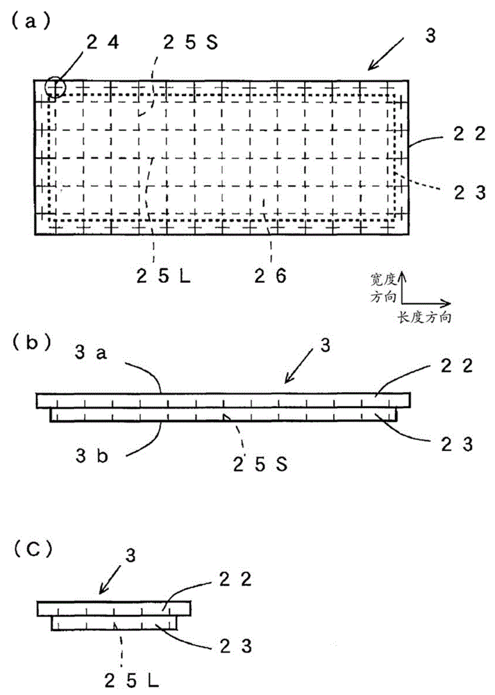
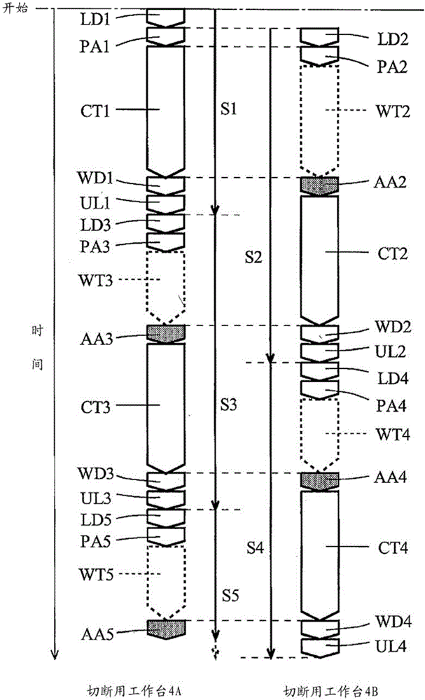
[0108] refer to Figure 1 to Figure 5 , an embodiment of the cutting device according to the present invention will be described. Any one of the drawings in this application document is appropriately omitted or exaggerated for easy understanding and is schematically depicted. The same reference numerals are used for the same structural elements, and explanations thereof are appropriately omitted.

[0109] figure 1 It is a schematic plan view showing the double-station type cutting device 1 according to the present embodiment. The cutting device 1 singulates an ob...


PUM


Abstract

The present invention provides a cutting device and cutting method. Even if thermal deformation is performed on a package substrate and a cutting line has position offset from a pre-alignment moment, cutting also can be performed in the way that offset of the cutting line is corrected before the cutting is about to begin. In the cutting device (1) in the form of double stations, a camera (13) used for notch detection, which is integrally arranged on a mandrel unit (10B), is used to shoot an alignment mark before the package substrate (3) is about to be cut. Even if the package substrate (3) is cooled under the influence of cutting water and cooling water and is in a contractive state, the offset from the cutting line set in the pre-alignment moment can be corrected by a control unit (CTL) before the cutting is about to begin based on the shot position of the alignment mark. And the package substrate (3) can be cut along the corrected cutting line.

Description

technical field [0001] The present invention relates to a cutting device and a cutting method for manufacturing a plurality of singulated electronic components by cutting an object to be cut. Background technique [0002] A substrate composed of a printed circuit board or a lead frame is virtually divided into a plurality of grid-shaped areas, and a chip-shaped component is mounted in each area, and the entire substrate is resin-encapsulated. The substrate is called a package substrate. An electronic component is obtained by cutting the package substrate by using a cutting device such as a rotary blade, and singulating each region. [0003] Conventionally, a cutting device is used to cut a predetermined region of a package substrate by a cutting mechanism such as a rotary blade. For example, a BGA (Ball Grid Array Package) product is cut in the following manner. First, the package substrate is placed on the cutting table at the substrate placement position with the substra...

Claims


Application Information

Patent Timeline
Patent Type & Authority Applications(China)
IPC IPC(8): H01L21/78H01L21/301
CPCH01L21/30H01L21/67092H01L21/78H01L21/304H01L21/76
Inventor 片冈昌一望月启人
Owner TOWA
Learn More