
Electronic device

A technology of electronic devices and electronic modules, which is applied in the direction of electrical digital data processing, instruments, cooling/ventilation/heating transformation, etc., can solve the problems of shortened working life, high working temperature, and inability to dissipate heat, so as to improve the heat dissipation effect and improve The effect of the flow path

Inactive Publication Date: 2015-03-18
HONG FU JIN PRECISION IND (SHENZHEN) CO LTD +1
View PDF5 Cites 2 Cited by
  • Summary
  • Abstract
  • Description
  • Claims
  • Application Information

AI Technical Summary

Problems solved by technology

Without a special heat dissipation design, the electronic modules in the rear row will not be able to dissipate heat effectively because the air flow has been preheated by the electronic modules in the front row, which will cause the working temperature of the electronic modules in the rear row to be too high. And greatly shorten its working life

Method used

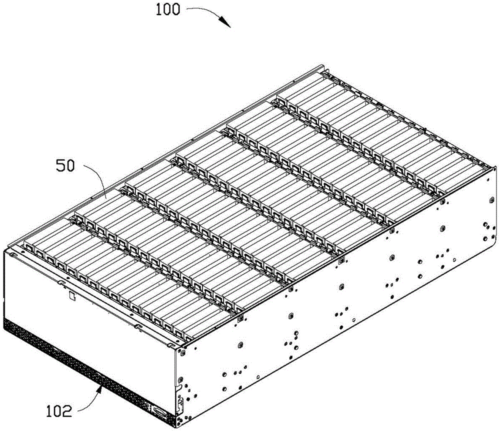
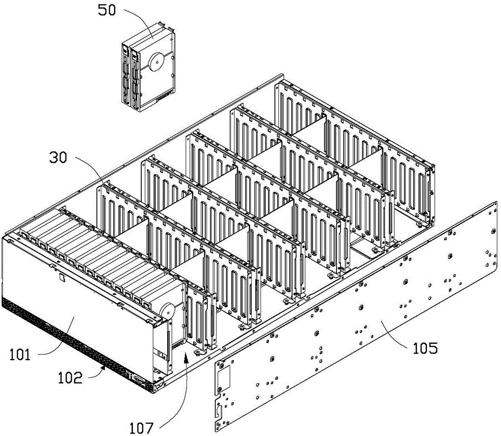
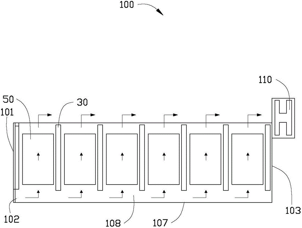

Image

  • Electronic device
  • Electronic device
  • Electronic device

Examples


Embodiment Construction

[0013] Please refer to figure 1 and figure 2 , The electronic device of the present invention includes a chassis 100 and several groups of electronic modules 50 , the chassis 100 includes a front panel 101 , a rear panel 103 , two side panels 105 , a bottom panel 107 and several partitions 30 . The partitions 30 are arranged in parallel between the front panel 101 and the rear panel 103 and vertically connected to the two side panels 105 respectively. The bottom of each partition 30 maintains a gap 108 with the bottom panel 107 . A cooling channel is formed between every two adjacent partitions 30 . Each group of electronic modules 50 is vertically inserted between two adjacent partitions 30 . An air inlet 102 is defined at the bottom of the front panel 101 . In this embodiment, the electronic module 50 is a hard disk module.

[0014] Please also refer to image 3 , when the electronic device of the present invention is working, the wind flow, such as external cold air, ...


PUM


Abstract

An electronic device comprises a chassis, a plurality of separation plates and a plurality of electronic modules; the plurality of separation plates are separately arranged in the chassis in a straddled mode; every electronic module is arranged between the two corresponding adjacent separation plates; the chassis comprises a front plate, a rear plate, two lateral plates and a base plate; the separation plates are separately arranged between the front plate and the rear plate in a parallel mode and perpendicularly connected with the two lateral plates; the bottom of the front plate is provided with an air inlet; a gap is formed between the bottom of every separation plate and the base plate; the air flow enters the chassis from the air inlet and flows between every two adjacent separation plates through the gap formed at the bottom of every separation plate to perform heat dissipation on the electronic module which is arranged between the two adjacent separation plates and the air flow after heat dissipation passes above the electronic module to flow out of the rear plate. According to the electronic device, a heat dissipation channel is formed between every two adjacent separation plates and accordingly the flow path of the air flow is improved, the division on the air flow is implemented, and the heat dissipation effect of the electronic device is improved.

Description

technical field [0001] The invention relates to an electronic device. Background technique [0002] Common electronic devices, such as servers, computers, etc., often add electronic module hard disks in order to improve their working performance, such as in order to increase storage capacity. The added electronic module hard disks are generally arranged in multiple rows and columns. Without a special heat dissipation design, the electronic modules in the rear row will not be able to dissipate heat effectively because the air flow has been preheated by the electronic modules in the front row, which will cause the working temperature of the electronic modules in the rear row to be too high. And greatly shorten its working life. Contents of the invention [0003] In view of the above, it is necessary to provide an electronic device capable of effectively dissipating heat from the hard disk. [0004] An electronic device includes a case, a plurality of partitions erected in...

Claims


Application Information

Patent Timeline
IPC IPC(8): G06F1/20H05K7/20
CPCG06F1/20G06F2200/202
Inventor 魏钊科范丽芳
Owner HONG FU JIN PRECISION IND (SHENZHEN) CO LTD
Learn More