Eureka AIR delivers breakthrough ideas for toughest innovation challenges, trusted by R&D personnel around the world.

Intelligent LED street lamp and control method for LED street lamps

A LED street lamp and LED lighting technology, which is applied in energy-saving control technology, circuit layout, lamp circuit layout, etc., can solve the problems of increased wiring costs, high cost, and the inability to truly achieve secondary energy saving of LED street lamps, so as to save power and brightness The effect of secondary energy saving

Inactive Publication Date: 2015-03-18
河南新飞利照明科技有限责任公司
View PDF6 Cites 14 Cited by
  • Summary
  • Abstract
  • Description
  • Claims
  • Application Information

AI Technical Summary

Problems solved by technology

Although these methods can achieve the purpose of dimming and energy saving, there are the following problems: the control is complicated, which reduces the reliability of LED street lamps, and the cost is high. The use of separate laying of control lines increases wiring costs and increases the difficulty of energy-saving transformation of the system.
Even in some application projects, time relays are installed in the distribution box, and energy is saved by turning on the lights in the first half of the night and extinguishing half of the lights in the second half of the night. The above control methods can be said to be simple and crude, and require special The personnel set up the corresponding control devices in advance according to the seasonal characteristics, and they cannot dynamically adjust the brightness of the street lamps according to the real-time analysis of the road conditions. Although the operating power is reduced, the basic needs of lighting cannot be met, and traffic safety is caused. Certain potential safety hazards, can not really achieve the purpose of secondary energy saving of LED street lighting

Method used


Image

  • Intelligent LED street lamp and control method for LED street lamps
  • Intelligent LED street lamp and control method for LED street lamps

Examples


Embodiment Construction

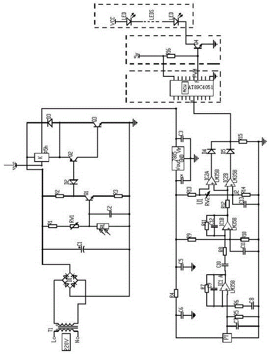
[0022] Such as figure 1 and figure 2 An intelligent LED street lamp shown includes a control processing unit, a light control unit, an infrared sensing unit, a dimming unit and an LED lighting unit;

[0023] Wherein, the LED lighting unit is arranged under the lampshade of the LED street lamp;

[0024] The infrared sensing unit includes a pyroelectric sensor arranged at the lower part of the LED street lamp lamp post in several adjacent road sections, and a sensor control unit electrically connected to the pyroelectric sensor;

[0025] The light control unit is set above the lampshade of the LED street lamp. The light control unit includes a power supply, a photosensitive sensing unit arranged above the lampshade of the LED street lamp, and a control execution unit. Execution unit connection, when the photosensitive sensing unit detects that the light in the surrounding environment is dimmed, the relay quickly conducts the infrared sensing unit, dimming unit and LED lightin...


PUM


Abstract

The invention provides an intelligent LED street lamp and a control method for LED street lamps. The intelligent LED street lamp comprises a control processing unit, a light control unit, an infrared sensing unit, a light-dimming unit and an LED lighting unit, wherein the LED lighting unit is arranged below the lampshade of the LED street lamp; the infrared sensing unit comprises pyroelectric sensors arranged at the lower portions of LED street lamp poles in a plurality of adjacent road segments and a sensor control unit electrically connected to the pyroelectric sensors; the light control unit is arranged above the lampshade of the street lamp, and comprises a power supply, a photosensitive sensing unit arranged above the lampshade of the street lamp and a control execution unit, and the power supply is respectively connected to the photosensitive sensing unit and the control execution unit. The intelligent LED street lamp can automatically monitor the brightness change of ambient light, the traffic flow and the vehicle speed, acquires the data of the ambient light and the road traffic conditions by the sensors, and then controls the light intensity of the LED street lamp after the data are processed.

Description

technical field [0001] The invention belongs to the field of LED lamps, and in particular relates to an LED street lamp capable of automatically adjusting light and shade according to traffic volume and light intensity. Background technique [0002] With the advancement of science and technology, a new generation of lighting fixtures using LED as the light source is gradually replacing traditional lighting fixtures in terms of functional lighting. It is well known for its high efficiency, safety, energy saving, environmental protection, long life, fast response, high color rendering index, and easy digital control. In recent years, with the acceleration of urbanization, the national government's increasing emphasis on energy conservation and emission reduction, and the promotion of "ten cities and ten thousand lamps" LED semiconductor lighting demonstration cities, LED street lights have sprung up in road lighting and developed rapidly. LED street lamp itself is undoubtedly...

Claims


Application Information

Patent Timeline
Patent Type & Authority Applications(China)
IPC IPC(8): F21S8/00F21V14/00F21V23/04H05B37/02F21W131/103
CPCF21S8/00F21V23/0464F21V23/0471F21W2131/103H05B47/105H05B47/11Y02B20/40
Inventor 程贞珠
Owner 河南新飞利照明科技有限责任公司
Why Eureka
Eureka Blog
Learn More