Hammer adjusting mechanism of lockstitch button holder

A technology of adjusting mechanism and buttonhole machine, which is applied to sewing machine components, tools for sewing clothes, textiles and papermaking, etc., can solve the problems of rising manufacturing costs, occupying operating space, and a large number of components, so as to reduce manufacturing costs and reduce occupied effect

Inactive Publication Date: 2015-03-18
CHEE SIANG IND CO LTD
View PDF4 Cites 0 Cited by
  • Summary
  • Abstract
  • Description
  • Claims
  • Application Information

AI Technical Summary

Problems solved by technology

[0006] However, the lack of this kind of buttonhole machine is that the overall drive mechanism that drives the horizontal movement of the cutting block is bulky and has a large number of components. In addition, it also takes up most of the operating space between the head and the base, which not only causes manufacturing costs The rise also causes operational inconvenience

Method used


Image

  • Hammer adjusting mechanism of lockstitch button holder
  • Hammer adjusting mechanism of lockstitch button holder
  • Hammer adjusting mechanism of lockstitch button holder

Examples


Embodiment Construction

[0030] In order to further have a clearer and more detailed understanding and understanding of the structure, use and features of the present invention, preferred embodiments are given, and the details are as follows in conjunction with the drawings:

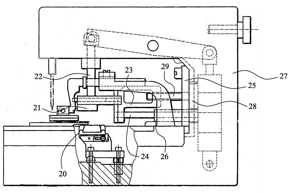
[0031] see image 3 As shown, the keyhole machine of the present invention mainly includes a headstock 30, a base 31 and a pillar 32, wherein the headstock 30 has an upper shaft 33, and one end of the upper shaft 33 is driven by a drive motor (not shown in the figure) ) to drive the rotation, the other end is provided with a needle bar 34 capable of reciprocating up and down, and the front end of the above-mentioned needle bar 34 is provided with a machine needle 35; a feeding table 36 is configured above the above-mentioned base 31, and this feeding table 36 can be The X and Y axis directions of the horizontal coordinates are shifted, and the above-mentioned feeding table 36 is provided with two pressing boards 37, and each pre...


PUM


Abstract

The invention provides a hammer adjusting mechanism of a lockstitch button holder. The hammer adjusting mechanism of the lockstitch button holder is applied to a sewing machine capable of adjusting the cutting length of buttonholes, and is provided with an upper side unit and a lower side unit, wherein the upper side unit is provided with a hammer; the hammer is vertically driven by a drive device to generate cutting action, and is driven by an adjusting device to generate horizontal-direction movement; the adjusting device is provided with a locating block arranged on the drive device, and is movably combined with a sliding seat connected with the hammer through the locating block; the sliding seat is driven by a drive source to horizontally move. According to the hammer adjusting mechanism of the lockstitch button holder, a group of cam mechanism is arranged between the sliding seat and the drive source and is provided with a rotary shaft, one end of the rotary shaft is connected with the drive source, the other end of the rotary shaft is assembled with a cam plate with a track, and a guiding pin designed on the sliding seat is arranged in the track in a penetrating way. Therefore, the quantity of components of the adjusting device can be simplified, and the occupation of the operation space of the lockstitch button holder can be also reduced.

Description

technical field [0001] The invention relates to a buttonhole machine for making buttonholes on sewn objects, in particular to a buttonhole machine capable of cutting buttonholes of different lengths only by adjusting the relative position of the hammer and the cutter without replacing parts. eyelet buttonhole machine. Background technique [0002] see Figure 1A and Figure 1B As shown, a known keyhole machine cutting buttonhole device has a fixed block 11 at one end of the shaft member 10 moving up and down, and a pneumatic cylinder 12 is built in the fixed block 11 and a cylinder that is linked with the pneumatic cylinder 12 The sliding mechanism 13 is provided so that the sliding mechanism 13 can automatically slide along the Y-axis direction, and a hammer 14 is fixed at the lower end of the sliding mechanism 13 . [0003] When this kind of buttonhole machine punches holes on the cloth, the hammer 14 is first moved laterally to the right to the position a1, and then the...

Claims


Application Information

Patent Timeline
IPC IPC(8): A41H25/00
CPCD05B37/02
Inventor 陈满雄
Owner CHEE SIANG IND CO LTD
Why Eureka
Try Eureka