
Circumferential block structure of prefabricated rectangular shield tunnel lining

A technology of rectangular shield and block structure, applied in tunnel lining, tunnel, wellbore lining, etc., can solve the problem of no clear definition of segment segments, increased opening of segment joints, unfavorable tunnel stress and waterproofing, etc. problems, to achieve good resistance to external soil loads, improve tunnel stress and waterproof capacity, and ensure the effect of lining stress performance

Active Publication Date: 2017-01-18
SHANGHAI URBAN CONSTR DESIGN RES INST GRP CO LTD
View PDF5 Cites 0 Cited by
  • Summary
  • Abstract
  • Description
  • Claims
  • Application Information

AI Technical Summary

Problems solved by technology

The commonly used circular shield segment has many mature segment division forms, but the shape of the rectangular shield segment is different from that of the circle, and the method of segment division has not been clearly defined; in addition, the applicant It is found that rectangular shield tunnels are mainly subject to bending, which is different from traditional circular shield tunnels. If no distinction is made and improvements are made, the circular block structure or block method of the lining of circular shield tunnels can be used directly to carry out segment Assembling the structural lining, the opening of the segment joints after loading will increase, which is very unfavorable for the tunnel’s stress and waterproofing, and further improvement is needed

Method used


Image

  • Circumferential block structure of prefabricated rectangular shield tunnel lining
  • Circumferential block structure of prefabricated rectangular shield tunnel lining

Examples


Embodiment Construction

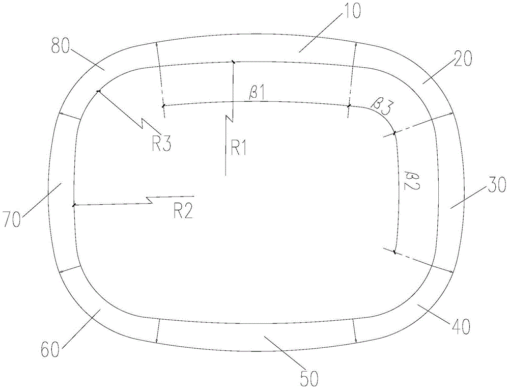
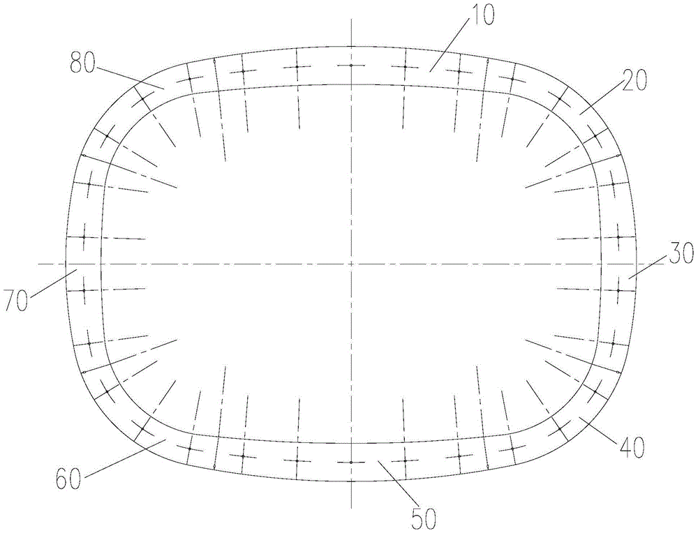
[0018] Such as figure 1 As shown, the ring block structure of a prefabricated rectangular shield tunnel lining in this embodiment consists of top inverted arch block 10, first corner block 20, first side wall block 30, The second corner block 40, the bottom inverted arch block 50, the third corner block 60, the second side wall block 70 and the fourth corner block 80 are connected in series, and the fourth corner block 80 is also separated from the top inverted arch. Blocks 10 are connected to form a closed circle as a whole, and the seams between adjacent blocks are located at places where the lining is less stressed.

[0019] The inner arc radius R1 of the top inverted arch block 10 and the bottom inverted arch block 50 of this embodiment is both 24000mm-26000mm, the angle β1 is 10°-12°, the first side wall block 30 and the second side wall The inner arc radius R2 of the wall block 70 is 14000mm-16000mm, the angle β2 is 38°-42°, the first corner block 20, the second corner ...


PUM


Abstract

The invention discloses an annular partitioning structure of an assembled type rectangular shield tunnel lining. The annular partitioning structure consists of a top inverted arch partitioning block, a first corner part partitioning block, a first side wall partitioning block, a second corner part partitioning block, a bottom inverted arch partitioning block, a third corner part partitioning block, a second side wall partitioning block and a fourth corner part partitioning block which are connected in series in sequence in the annular direction, wherein the fourth corner part partitioning block is also connected with the top inverted arch partitioning block to integrally form a closed ring in a surrounding manner; splicing joints between the adjacent partitioning blocks are positioned at positions, which are lower in stress, on the lining. The splicing joints of all the partitioning blocks are positioned at positions, which are lower in stress, on the lining, so that stress on the partitioning blocks can be easily met; correspondingly, the partitioning blocks at the regions, which are higher in stress, on the lining are continuously arranged, so that the stress performance of the lining is effectively guaranteed; therefore the annular partitioning structure of the lining can better adapt to the stress characteristic of a rectangular shield tunnel, and the water resistance and the waterproofing capacity of the tunnel are effectively improved.

Description

technical field [0001] The invention relates to the technical field of structural design of shield tunnel lining, in particular to a ring-direction block structure of an assembled rectangular shield tunnel lining. Background technique [0002] With the development of science and technology, a rectangular shield tunneling method suitable for soft soil areas has been deeply studied at home and abroad. The rectangular shield tunnel can make full use of the structural section, effectively reducing the tunnel depth and cost. The commonly used circular shield segment has many mature segment division forms, however, the shape of the rectangular shield segment is different from that of a circle, and the method of segment division has not been clearly defined; in addition, the applicant It is found that the rectangular shield tunnel is mainly subjected to bending, which is different from the traditional circular shield tunnel. If no distinction is made and improvements are made, the...

Claims


Application Information

Patent Timeline
Patent Type & Authority Patents(China)
IPC IPC(8): E21D11/00
CPCE21D11/00
Inventor 张银屏袁自鸣欧阳文彪潘国庆姜弘包鹤立
Owner SHANGHAI URBAN CONSTR DESIGN RES INST GRP CO LTD
Learn More