Control method of flexible drive unit for robot joints with tension and joint position feedback
A technology for robot joints and drive units is applied in the control field of flexible drive units for robot joints and flexible drive units for robot joints.
- Summary
- Abstract
- Description
- Claims
- Application Information
AI Technical Summary
Problems solved by technology
Method used
Image
Examples
specific Embodiment approach 1
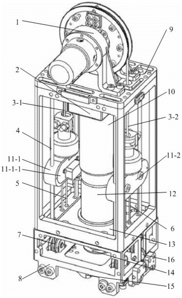
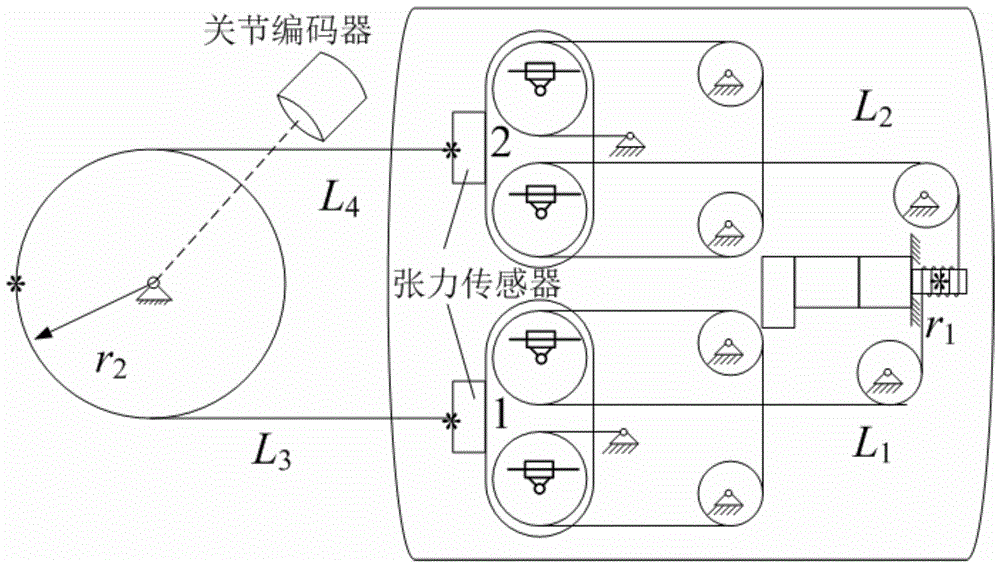
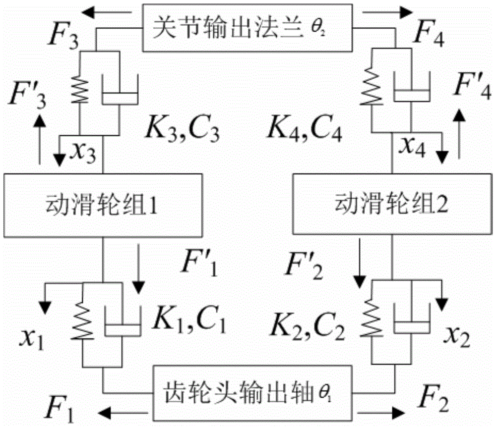
[0069] Specific implementation mode one: as Figure 1-11 As shown, the flexible drive unit control method for robot joints described in this embodiment that can realize tension feedback and joint position feedback uses the viscoelastic dynamics model of the flexible drive unit to perform joint position and joint speed feedback, and performs the feedback according to the elastic deformation of the steel wire rope. Feedforward for joint velocity and joint acceleration. Joint position and speed feedback, that is, the position loop and speed loop of the joint are introduced on the basis of the internal position loop and speed loop of the motor to realize the full closed-loop control of the joint of the flexible drive unit. For the speed and acceleration feedforward of elastic deformation, the basic idea is that the elongation of the steel wire rope can be obtained through the elastic deformation formula, and the speed and acceleration that need to be fed forward can be obtained fr...
specific Embodiment approach 2
[0109] Specific implementation mode two: the block diagram of the controller designed according to the control method and its principle diagram are as follows Figure 4 shown. The solid line part is the classic PID servo control link, and the dotted line part is the supplementary control link according to the control method. The controller generates the joint angle and angular velocity sequence through the trajectory generator of the host computer, and sends it to the motion control card for servo interpolation calculation. Before the servo interpolation calculation, the joint angle and angular velocity are fed back first. Carry out four arithmetic operations and differentiation on the joint angle formula derived from science, and the obtained joint angle and angular velocity estimates are used to feed back the joint reference angle and angular velocity; after the servo interpolation calculation, the velocity and acceleration are fed forward. The deformation of the steel wire ...
specific Embodiment approach 3
[0110] Specific implementation mode three: Application example 1 of this patent, that is, the hardware photo of the flexible drive unit control system built according to the control method is as follows Figure 5 As shown in a), the schematic diagram is as follows Figure 6 shown. The upper computer performs trajectory planning and sends the planned instructions to the PMAC motion control card. The PMAC motion control card communicates with the upper computer through Ethernet and sends the motion program to the PMAC. The PMAC can upload the program or system status to the upper computer; The driver is controlled by PFM mode, the driver amplifies the signal and sends it to the motor; the motor encoder A phase, B phase, I (index) signal is fed back to the driver and PMAC motion control card at the same time; the joint encoder feeds back the A, B, I signal to The PMAC card constitutes a fully closed-loop control; the enable control of the motor driver is performed according to t...
PUM
 Abstract
Description
Claims
Application Information
 - R&D
- Intellectual Property
- Life Sciences
- Materials
- Tech Scout
- Unparalleled Data Quality
- Higher Quality Content
- 60% Fewer Hallucinations
Browse by: Latest US Patents, China's latest patents, Technical Efficacy Thesaurus, Application Domain, Technology Topic, Popular Technical Reports.
© 2025 PatSnap. All rights reserved.Legal|Privacy policy|Modern Slavery Act Transparency Statement|Sitemap|About US| Contact US: help@patsnap.com


