An automatic tin feeding laser welding method

A laser welding and automatic technology, applied in the direction of tin feeding device, welding equipment, metal processing equipment, etc., can solve the problems of damage to heat-sensitive components, uncontrollable amount of tin, uncontrollable state of tin wire on pads, etc., to achieve Prevent bending and wire plugging, avoid welding failure, uniform and reliable welding effect

Active Publication Date: 2017-12-19
WUHAN LINGYUN PHOTOELECTRONICS SYST
View PDF9 Cites 0 Cited by
  • Summary
  • Abstract
  • Description
  • Claims
  • Application Information

AI Technical Summary

Problems solved by technology

[0004] In the traditional method, the tin wire comes out directly at the welding point, and the tin wire is easily hindered by the welding point, causing the tin wire to bend, block the wire, and change the position of the starting point of the tin wire before and after welding. This series of factors lead to the failure of the tin wire The state is uncontrollable, resulting in an uncontrollable amount of tin. If the amount of tin is small, the heat of the pad will still be excessive, causing the pad to burn. If the amount of tin is too much, the heat of the pad will not be enough, causing the tin to form balls after melting without infiltrating the pad. , forming virtual welding
In addition, since the tin wire absorbs heat and the pad absorbs heat, the lead wire on the pad will also absorb heat. In addition to the stable and controllable heat dissipation of the tin wire, the heat dissipation of the solder pad and the lead wire varies greatly. To make the tin wire It can melt smoothly without causing damage to pads and components. This series of factors further increases the difficulty of reasonably controlling the state of tin wire
In addition, the laser focus is directly irradiating the solder joint during welding, which has great potential damage to heat-sensitive components.
In the existing situation, it is difficult to achieve continuous welding by avoiding the laser focus on the pad for a long time and solving the uncontrollable state of the tin wire.

Method used


Image

  • An automatic tin feeding laser welding method
  • An automatic tin feeding laser welding method
  • An automatic tin feeding laser welding method

Examples


Embodiment Construction

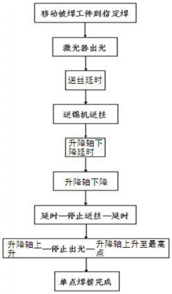
[0034] In order to make the object, technical solution and advantages of the present invention clearer, the present invention will be further described in detail below in conjunction with the accompanying drawings and embodiments. The specific embodiments described here are only used to explain the present invention, not to limit the present invention. In addition, the technical features involved in the various embodiments of the present invention described below can be combined with each other as long as they do not constitute a conflict with each other.

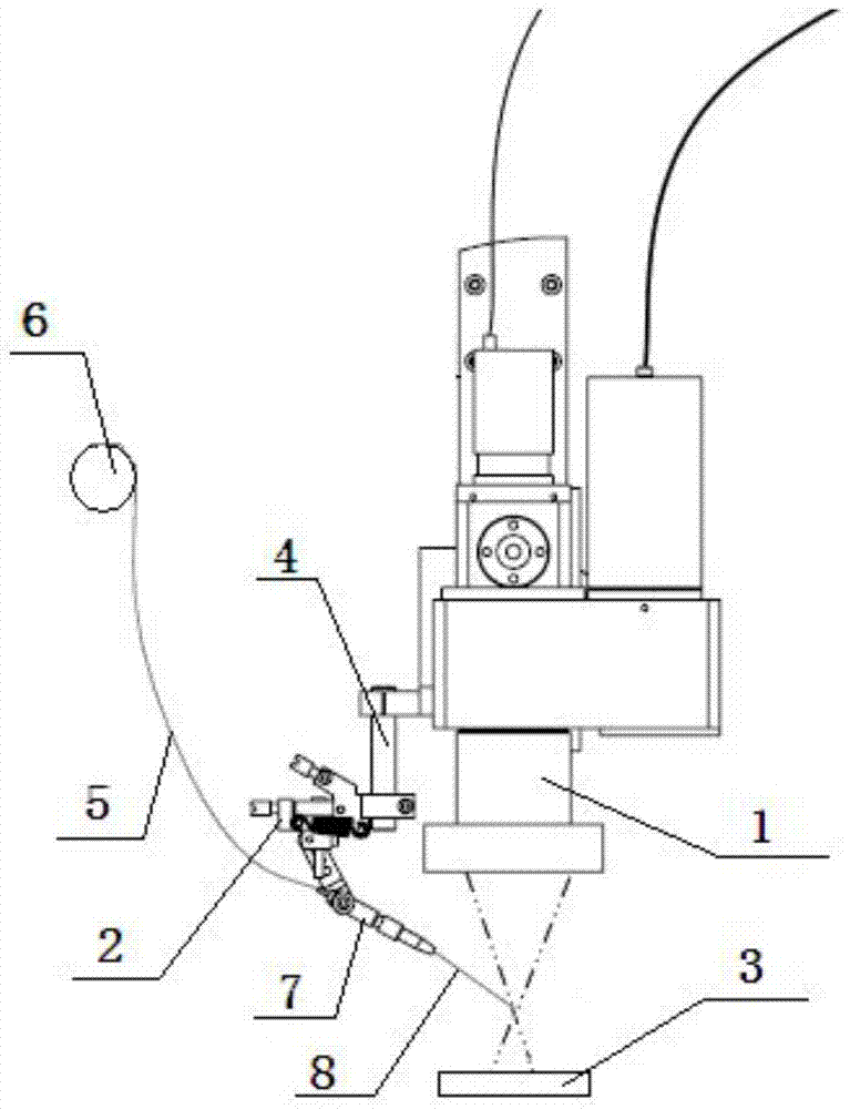
[0035] Such as figure 1 As shown, the present invention includes an automatic tin feeder 2, a laser 1 and a welding workbench 3. The upper end surface of the welding workbench 3 is located below the focal point of the output laser of the laser 1 (the dotted line shown in the figure is the output laser, and the intersection of the two dotted lines is The output focus of the laser), the automatic tin feeding machine include...


PUM

PropertyMeasurementUnit
Defocus amountaaaaaaaaaa

Abstract

The invention relates to the field of laser welding, in particular to an automatic tin feeding laser welding method. A laser outputs laser to pre-heat welded workpieces by adopting a positive defocus way; tin wires are then output to a laser focus part, are melted to form tin balls, and are downwards moved to the part of the welded workpieces; the tin balls soak welding points through continuous laser irradiation; the tin wires are finally moved upwards to the initial position. According to the automatic tin feeding laser welding method, the stability in tin wire discharge can be ensured, the tin wires can be quickly melted after being in contact with the welding points, the focus of the laser is not in direct contact with the welding points, and thermosensitive elements surrounding a welding pad are prevented from being influenced by high temperature during welding.

Description

technical field [0001] The invention relates to the field of laser welding, in particular to an automatic tin-feeding laser welding method. Background technique [0002] The traditional automatic tin-feeding laser welding method is completed by controlling the laser and the tin-feeding mechanism. It can complete the welding of 3C electronic products, and is also capable of welding heat-sensitive components with low temperature requirements. [0003] Such as figure 2 Shown is the flow of the traditional welding method, which is divided into the following steps: ⑴ move the workpiece to be welded to the predetermined welding position; ⑵ the laser emits laser light with a predetermined current or energy to irradiate the welding point; ⑶ set a sender The wire feeding delay of the tin mechanism enables the laser to fully preheat the solder joints; (4) The tin feeding mechanism sends the tin wire to the solder joint, and the tin wire melts and infiltrates the pad under the action ...

Claims


Application Information

Patent Timeline
Patent Type & Authority Patents(China)
IPC IPC(8): B23K1/005B23K3/06
CPCB23K1/0056B23K3/0607
Inventor 罗桥杨明王锋
Owner WUHAN LINGYUN PHOTOELECTRONICS SYST
Why Eureka
Try Eureka