
A dual-channel annular gas distribution device

A gas distribution device and a technology for gas distribution, applied in the direction of fractionation, etc., can solve the problems of long gas diffusion path, difficult gas uniform distribution, unfavorable installation and maintenance of the distributor, etc., so as to increase the degree of freedom of radial diffusion and simple structure. , the effect of convenient installation and maintenance

Active Publication Date: 2016-09-28
HANGZHOU HANGYANG
View PDF6 Cites 0 Cited by
  • Summary
  • Abstract
  • Description
  • Claims
  • Application Information

AI Technical Summary

Problems solved by technology

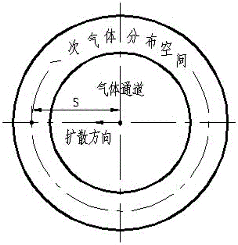
For the convenience of description, for a gas channel with a circular or circular cross section, the gas radial inward diffusion and radial outward diffusion are defined as its two radial diffusion degrees of freedom (especially, the circular gas channel There is only one degree of freedom for radially outward diffusion, and the annular gas channel with the inner wall of the tower as the outer annulus has only one degree of freedom for radially inward diffusion), and at the same time, the center of the gas channel is directly above the primary gas distribution space. The distance between the centers is defined as the gas diffusion path S, obviously, figure 1 The gas distributor in the model has only one radially outward diffusion degree of freedom. For larger towers, the gas diffusion path S is too long, and it is difficult to achieve the effect of uniform gas distribution. Tight fit is also not conducive to the installation and maintenance of the distributor

Method used


Image

  • A dual-channel annular gas distribution device
  • A dual-channel annular gas distribution device
  • A dual-channel annular gas distribution device

Examples


Embodiment Construction

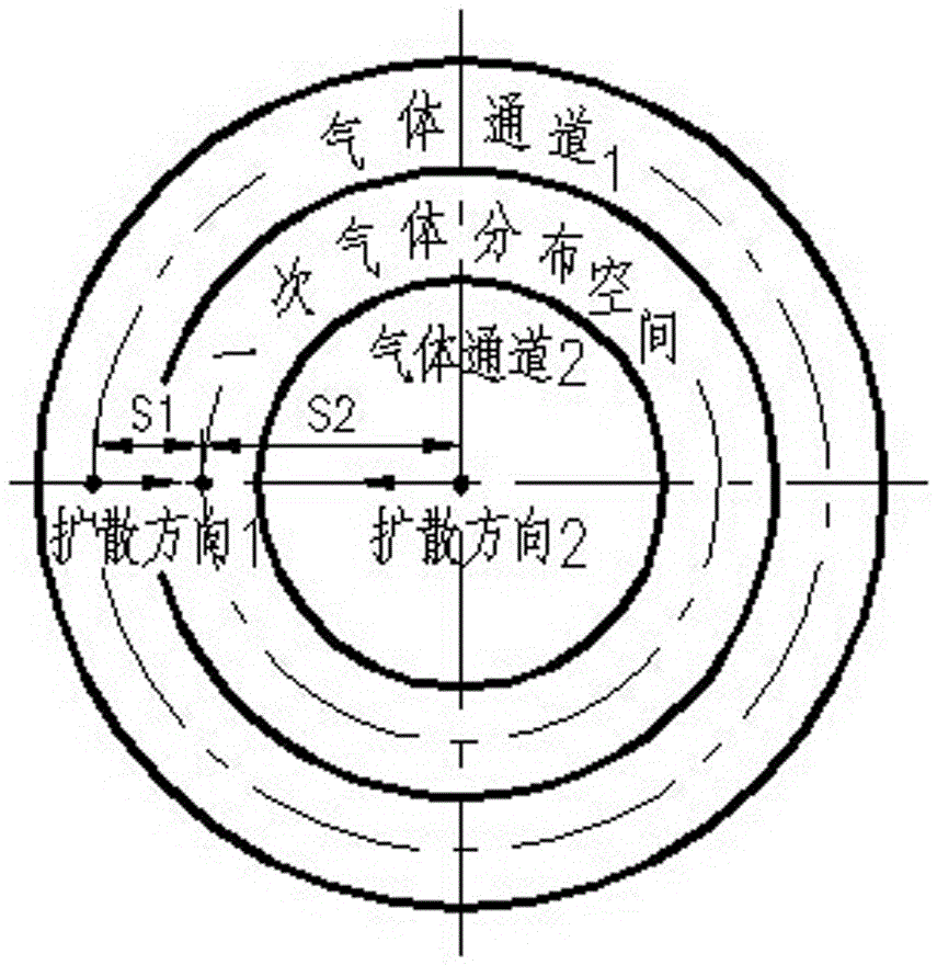
[0016] Below in conjunction with accompanying drawing, the present invention will be further described: figure 2 As shown, the present invention is a technical improvement to the existing gas distributor. It separates the primary distribution space of the distributor, thereby creating an annular gas channel 1 between the gas distributor and the inner wall of the tower, and the gas flows from the primary After the gas distribution space comes out, it is divided into two parts from gas channel 1 and gas channel 2 to reach the top of the distributor, and then each diffuses to the top of the primary gas distribution space of the distributor. At this time, the gas has two radial diffusion degrees of freedom: gas The degree of freedom of radial inward diffusion of channel 1 and the degree of freedom of radial outward diffusion of gas channel 2, the gas in each channel has a short diffusion path S1, S2, so that the gas can be quickly and effectively distributed in the top space of th...


PUM


Abstract

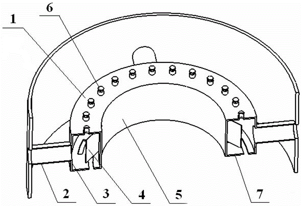
A double-channel annular gas distribution device, which includes a top plate, an air induction pipe, an outer cylinder, a deflector, an inner cylinder, and a gas distribution plate, and the outer cylinder and the top plate, the inner cylinder, and the gas distribution plate are welded to form an independent Annular primary gas distribution space, an annular gas distribution channel is formed between the outer cylinder and the inner wall of the tower; the air induction pipe and the gas inlet pipe are arranged coaxially; the deflectors are symmetrically arranged with the center section of the tower as a symmetrical plane ; The top plate is provided with lift passages for a small part of the gas to move upwards and uniformly distributed along the circumference; the gas distribution plate is located below the annular primary gas distribution space, and its specific structure is in the form of a deflector or a uniform The ring plate form of the gas distribution hole mainly provides the main gas flow to move downward, and enables the gas flow to collide with the liquid at the bottom of the tower and then fold and move upward; it has the advantages of simple structure, reasonable economy, safety and stability, and excellent performance.

Description

technical field [0001] The invention relates to a double-channel annular gas distribution device for gas-phase feeding of a large or super-large tower container, which is an important part widely used in rectification equipment such as air separation and chemical industry, and belongs to energy-related air separation and chemical equipment. Gas distribution technology field. Background technique [0002] With the rapid development of my country's industry, the demand for oxygen, argon, and nitrogen in iron and steel smelting, petrochemical, coal chemical, and fertilizer industries has increased sharply, which has led to the development of extra-large rectification towers, and the gas and liquid in the tower The uniform distribution of is the main problem of column scale-up. At the same time, with the continuous advancement of packing technology, the development of new high-efficiency packing with large void ratio and low pressure drop has higher and higher requirements for t...

Claims


Application Information

Patent Timeline
Patent Type & Authority Patents(China)
IPC IPC(8): B01D3/16
Inventor 文顺清顾燕新裴洪敏康康尹路黄剑能何珍珍卢炳攀
Owner HANGZHOU HANGYANG
Learn More