
Low-frequency high-power resonator and electrically tunable band stop filter

A high-power, resonator technology, applied in the field of low-frequency resonators and electronically tuned band-stop filters, low-frequency high-power resonators and electronically tuned band-stop filters, can solve the problem of small passing power, ignition breakdown, and resonator Long and other problems, to achieve the effect of low power withstand, high power withstand, and reduced length

Active Publication Date: 2015-03-04
NO 54 INST OF CHINA ELECTRONICS SCI & TECH GRP
View PDF9 Cites 5 Cited by
  • Summary
  • Abstract
  • Description
  • Claims
  • Application Information

AI Technical Summary

Problems solved by technology

[0004] Resonators realized in traditional ways, when used in the low frequency band, either the resonator is long and large in size, or the volume can be small but the passing power is also small, and when it is applied to high-power microwaves, there will be a phenomenon of spark breakdown

Method used


Image

  • Low-frequency high-power resonator and electrically tunable band stop filter
  • Low-frequency high-power resonator and electrically tunable band stop filter
  • Low-frequency high-power resonator and electrically tunable band stop filter

Examples


Embodiment 1

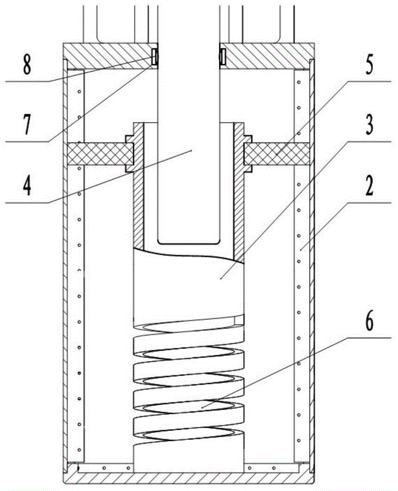
[0027] A low-frequency high-power resonator 10, including an outer conductor 2, is characterized in that: it also includes an inner conductor 3, a tuning rod 4, and a dielectric support 5, the inner conductor 3 is fixedly installed at the bottom of the outer conductor 2, and the top is provided with Groove 7, the finger reed 8 of beryllium bronze material is housed in the groove 7, the tuning rod 4 extends into the inner conductor 3 from the groove 7, and is in elastic short-circuit contact with the finger reed 8 The inner conductor 3 is a hollow metal cylinder, which is in conductive contact with the outer conductor 2, and the middle and lower part of its outer wall is provided with a hollow spiral track slot 6; the outer wall of the inner conductor 3 is provided with two layers of raised grooves , the dielectric support 5 perpendicularly intersects the inner conductor 3 and is fixedly installed in the two-layer raised groove on the outer wall of the inner conductor 3 . The t...

Embodiment 2

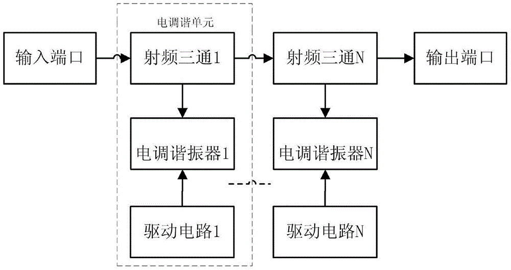
[0030] Such as figure 2 Shown, a kind of high-power electronically tuned band-stop filter with the low-frequency high-power resonator described in Embodiment 1 is made up of an input interface, an output interface, and more than one electrical tuning unit with the same structure; the input port, The corresponding input / output interfaces and output ports of each electrical tuning unit are sequentially connected through radio frequency transmission lines; each electrical tuning unit is composed of a radio frequency tee, a drive circuit, and an electrical tuning resonator.

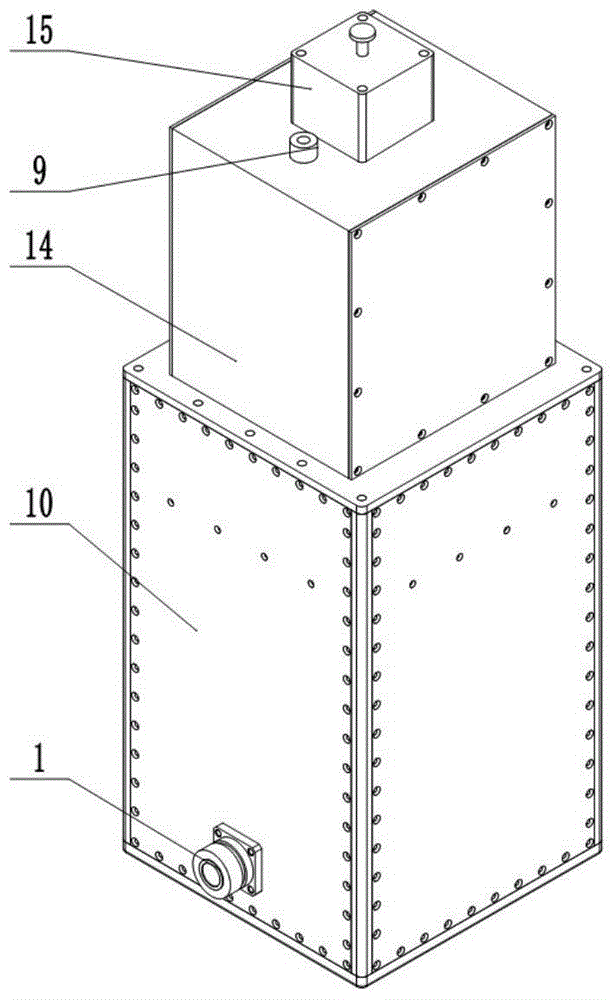
[0031] Such as image 3 and Figure 4 As shown, the corresponding input terminals of the electronically tuned resonator are respectively connected to the corresponding output terminals of the radio frequency tee and the driving circuit; , a linear motor 15 and the low-frequency high-power resonator 10. The radio frequency interface 1 is assembled on the outer conductor 2 of the low-frequency high-power re...


PUM


Abstract

The invention discloses a low-frequency high-power resonator and an electrically tunable band stop filter with the low-frequency high-power resonator. The low-frequency high-power resonator comprises an outer conductor, an inner conductor, a tuning post and a medium support, wherein the inner conductor is fixedly arranged at the bottom of the outer conductor, and the top of the outer conductor is provided with a groove; a finger-type reed of a beryllium bronze material is arranged in the groove; the tuning post extends into the inner conductor from the groove and is in elastic short-circuit contact with the finger-type reed; the inner conductor is a hollow metal column and is in electric contact with the outer conductor, and the middle lower part of the outer wall of the inner conductor is provided with a hollow spiral track groove; the outer wall of the inner conductor is provided with two layers of convex grooves; the medium support is vertically crossed with the inner conductor and is fixedly arranged in the two layers of convex grooves in the outer wall of the inner conductor. The high-frequency electrically tunable band stop filter consists of an input interface, an output interface and more than one electric tuning unit which are connected in sequence. Electric frequency change of the band stop filter is realized, and the requirements of small size, wide tuning frequency range and high power at an ultralow frequency band can also be met.

Description

technical field [0001] The invention relates to a low-frequency resonator and an electric tuned band-stop filter, in particular to a low-frequency high-power resonator and an electric tuned band-stop filter, belonging to the technical field of microwave filters. Background technique [0002] In the prior art, "Design of a high-power narrow-band electronically tuned filter" in the fifth issue of "Telecommunications Technology" in 2013, the resonator is an inner conductor with uniform impedance, and the resonance method of adding a tuning rod to the open end is adopted. Since the length of the inner conductor is very long when working at low frequency, it is only suitable for working in the high frequency band of the VHF band, so it has a large size and low power, and the electronically tuned filter is a band-pass filter and does not have a band-pass filter. The function of the blocking filter, and its resonator is only suitable for the filter of the hundred-watt class. [00...

Claims


Application Information

Patent Timeline
Patent Type & Authority Applications(China)
IPC IPC(8): H01P7/06H01P1/20
Inventor 李春红贾建蕊陈建国王晓龙马延爽
Owner NO 54 INST OF CHINA ELECTRONICS SCI & TECH GRP
Learn More