
Body deformation detection device based on laser conduction

A detection device and vehicle body technology, which is applied to measurement devices, optical devices, instruments, etc., can solve the problems of high cost, limited accuracy and limited accuracy, and achieve the effects of high directivity, improved accuracy and low detection cost.

Active Publication Date: 2017-02-22
ZHEJIANG UNIV
View PDF10 Cites 2 Cited by
  • Summary
  • Abstract
  • Description
  • Claims
  • Application Information

AI Technical Summary

Problems solved by technology

The mechanical three-dimensional system inspection uses a special inspection platform to accurately measure various dimensions, and then compares them with the factory data to finally determine the degree of deformation. Accuracy is limited, the accuracy of this technology is still relatively limited
Electronic measurement system detection uses computers and sensors to detect deformation, with high precision and accurate measurement, but the cost is the highest, and its practical application is not as extensive as mechanical three-dimensional system detection technology

Method used


Image

  • Body deformation detection device based on laser conduction
  • Body deformation detection device based on laser conduction

Examples


Embodiment 1

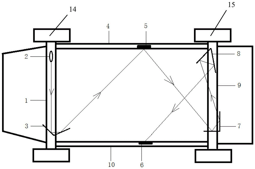
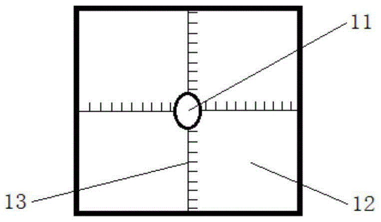
[0030] refer to Figure 1-2: A vehicle body deformation detection device based on laser conduction, comprising a front axle 1 of a car, a rear axle 9, and a first side bridge 4 and a second side bridge 10 on both sides, the front axle 1 is fixedly equipped with a laser 2 and A first metal reflector 3, a second metal reflector 5 is fixedly installed on the first side bridge 4, a third metal reflector 7 and a fourth metal reflector 8 are fixedly installed on the rear bridge 9, the The second side bridge 10 is fixedly installed with a receiving plate 6 that can detect the position of the laser, the first metal reflector 3, the second metal reflector 5, the third metal reflector 7, the fourth metal reflector 8, and the receiving plate 6 vertically. To set up, the laser 2 emits laser light, and reaches the receiving plate 6 through the first metal reflective plate 3, the second metal reflective plate 5, the third metal reflective plate 7, and the fourth metal reflective plate 8, an...

Embodiment 2

[0043] The difference between this embodiment and Embodiment 1 is that the laser is located at the lower end of the first metal reflector, the first side bridge is located at the lower end, the second side bridge is located at the upper end, and the third metal reflector is located at the fourth metal reflector the upper end. This embodiment is equivalent to the specular reflection structure relative to the horizontal line in the first embodiment.


PUM


Abstract

The invention relates to a car body deformation detector based on laser transmission. The car body deformation detector comprises a front axle of a car and a rear axle as well as a first lateral axle and a second lateral axle located at two sides; a laser unit and a first metal reflecting plate are arranged on the front axle; a second metal reflecting plate is arranged on the first lateral axle; a third metal reflecting plate and a fourth metal reflecting plate are arranged on the rear axle; a receiving plate capable of detecting laser positions is arranged on the second lateral axle; the first metal reflecting plate, the second metal reflecting plate, the third metal reflecting plate, the fourth metal reflecting plate and the receiving plate are arranged vertically; laser emitted by the laser unit arrives at the receiving plate via the first metal reflecting plate, the second metal reflecting plate, the third metal reflecting plate and the fourth metal reflecting plate; the deformation position and the deformation degree of the car body are judged by the laser position on the receiving plate. The car body deformation detector based on laser transmission is quick and convenient to detect the deformation position and the deformation degree of the car body, is capable of positioning the whole deformation of the car body and has low detection cost.

Description

technical field [0001] The invention relates to a car body deformation detection device. Background technique [0002] When a car is running on a rough road, the frame may produce torsional deformation and bending deformation in the longitudinal plane; when one side of the wheel encounters an obstacle, the entire frame may be distorted into a rhombus; when a collision occurs, the collision The energy will be absorbed by the body, causing it to deform, and these deformations will directly act on the body that is fixed to the frame, and the repeated action of the load will deform the body. The deformation of the body will affect the relationship between the components and the assembly installed on it, causing interference, and will also affect the position of the axle wheels, accelerate the wear of the tires, reduce the fuel economy of the vehicle, and affect the driving performance. The car body will be broken due to fatigue damage and cracks in some parts, resulting in seri...

Claims


Application Information

Patent Timeline
Patent Type & Authority Patents(China)
IPC IPC(8): G01B11/16
Inventor 熊树生钟剑锋
Owner ZHEJIANG UNIV
Learn More