
Feeding car for sawing machine

A technology for feeding trolleys and sawing machines, which is applied to the attachments of sawing machines, metal sawing equipment, clamping, etc., and can solve problems such as low efficiency in loading and unloading bars and difficulty in height adjustment

Inactive Publication Date: 2015-03-04
CHONGQING SHUAICHANG MACHINE MFG
View PDF0 Cites 5 Cited by
  • Summary
  • Abstract
  • Description
  • Claims
  • Application Information

AI Technical Summary

Problems solved by technology

[0004] The technical problem to be solved by the present invention is to provide a sawing machine feeding trolley with the characteristics of simple height adjustment and high efficiency of loading and unloading bars in view of the existing sawing machine support frame that has difficulty in height adjustment and low efficiency in loading and unloading bars

Method used


Image

  • Feeding car for sawing machine
  • Feeding car for sawing machine

Examples


Embodiment Construction

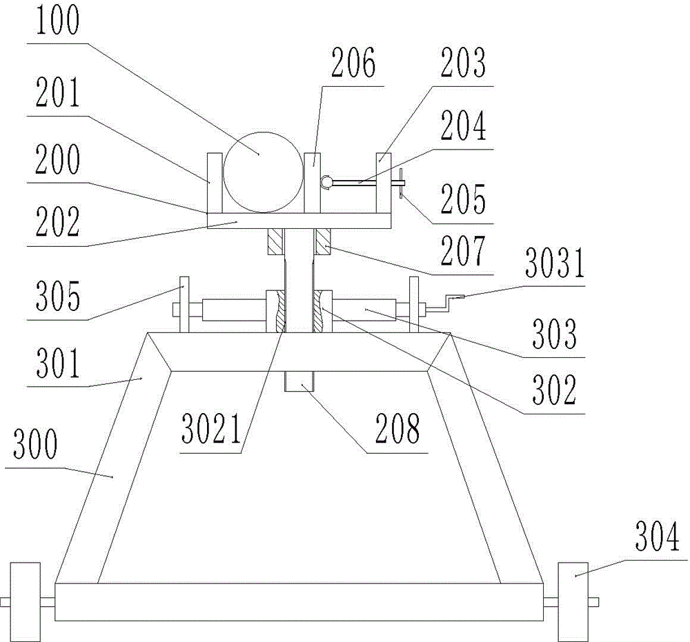
[0014] Such as figure 1 , figure 2 As shown, the feeding trolley of the sawing machine of the present invention is made up of support frame 300 and material frame 200, and material frame 200 comprises material bottom plate 202, material fixed baffle 201, material movable baffle 206, threaded hole plate 203, material fixed baffle 201 is positioned at material The left end of the bottom plate 202, the threaded orifice plate 203 is located at the right end of the material plate 202, and the material movable baffle 206 is located between the material fixed baffle 201 and the threaded orifice 203. A threaded rod 204 is provided between the material movable baffle 206 and the threaded orifice 203, the left end of the threaded rod 204 is ball-hinged with the material movable baffle 206, the threaded rod 204 is threadedly connected with the screwed orifice 203, and the right end of the threaded rod 204 is provided with Rotate rod 205, sleeve 207 is provided at the bottom of material...


PUM


Abstract

The invention discloses a feeding car for a sawing machine. In order to overcome the defects that height adjustment is difficult and bar handling efficiency is low by adopting the existing sawing machine support frame, the invention provides the feeding car for the sawing machine. The feeding car for the sawing machine comprises a support frame and a material shelf; the material shelf is located above the support frame; the material shelf comprises a material bottom plate, a material fixed baffle, a material movable baffle and a threaded pore plate; the material movable baffle is located between the material fixed baffle and the threaded pore plate; a threaded rod is arranged between the material movable baffle and the threaded pore plate; the bottom part of the material bottom plate is provided with a sleeve; a threaded shaft is arranged between the support frame and the material shelf; the sleeve is sheathed with the threaded shaft; the support frame comprises a support framework; the upper part of the support framework is provided with two worm support plates; a worm is arranged between the two worm support plates; the upper part of the support framework is also provided with a worm gear; a threaded hole is formed in the middle part of the worm gear; the worm gear is in threaded connection with the threaded shaft; the worm is meshed with the worm gear.

Description

technical field [0001] The invention belongs to the field of sawing machine auxiliary equipment, and in particular relates to a sawing machine feeding trolley. Background technique [0002] The sawing machine is a machine tool that uses circular saw blades, saw bands or saw blades as tools to saw metal round materials, square materials, pipe materials and profiles. The machining accuracy of the sawing machine is generally not very high, and it is mostly used in the material preparation workshop to cut various bars, pipes and other profiles. When the sawing machine is sawing the bar, usually one end of the bar is fixed on the workbench of the sawing machine, and the bar is supported by an auxiliary device, for example, one end of the bar is hung by driving, or one end of the bar is fixed on the The other end of the workbench of the sawing machine is fixed on the support frame. Yet existing sawing machine support frame is usually made up of support plate, pulley, support fra...

Claims


Application Information

Patent Timeline
IPC IPC(8): B23Q7/00B23Q3/00B23D59/00
CPCB23Q7/00B23D59/00B23Q3/00
Inventor 丁丽霞
Owner CHONGQING SHUAICHANG MACHINE MFG
Learn More