Automatic cable cutting off machine

An automatic cutting and cable technology, applied in metal processing, metal processing equipment, manufacturing tools, etc., can solve the problems of low precision, low work efficiency, inaccurate cable length, etc., and achieve simple structure setting, convenient cutting, The effect of easy maintenance

Inactive Publication Date: 2015-03-04
TIANJIN OULIN ELECTRONICS
View PDF6 Cites 2 Cited by
  • Summary
  • Abstract
  • Description
  • Claims
  • Application Information

AI Technical Summary

Problems solved by technology

[0003] During the processing of the data cable, the production and processing of the data cable requires a thread cutting process. The traditional method is to manually cut with the help of a knife. This manual cutting method has low work efficiency, and the labor load of the workers is large, and the length of the cable is not accurate. , the accuracy is not high, and after the cutting is completed, the method of manual measurement with a tape measure is used. This method is not only time-consuming but also difficult to achieve the accuracy of cutting. The low production efficiency directly leads to the reduction of the production efficiency of the enterprise, which is not conducive to the development of data lines. Mass production, therefore, we want to research a new type of thread cutting tool to solve the troubles and difficulties encountered in manual thread cutting

Method used


Image

  • Automatic cable cutting off machine
  • Automatic cable cutting off machine
  • Automatic cable cutting off machine

Examples


Embodiment Construction

[0026] The present invention will be described in detail below in conjunction with the accompanying drawings.

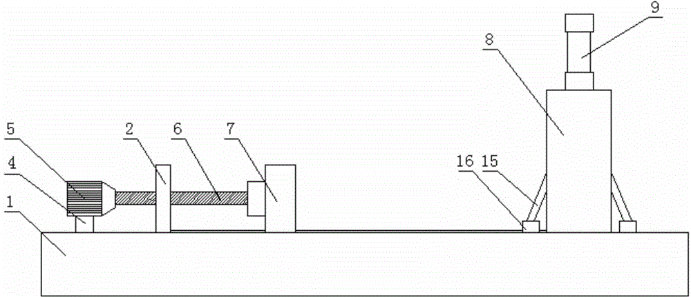
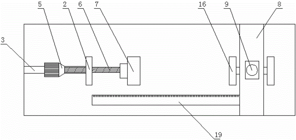
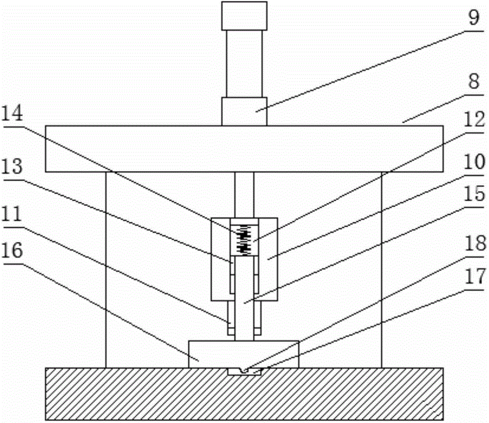
[0027] Such as Figure 1-Figure 3 As shown in the schematic diagram of the structure of the present invention, the present invention provides an automatic cable cutting machine, including a base 1, on which a measuring device and a shearing device are sequentially arranged on the base 1, and the measuring device includes a fixing plate fixed on the base 1 2. A slideway 3 is provided on the base 1 on the left side of the fixed plate 2, and a slider 4 is arranged in the slideway 3. The motor 5 is fixed on the slider 4. The output end of the motor 5 is connected to the adjustment screw 6, and the adjustment screw 6 passes through the fixed plate 2 and rotates to connect the measuring plate 7; the shearing device includes a support 8 fixed on the base, and a cylinder 9 is arranged on the top plate of the support 8, and the front end of the piston rod of the cylinder 9 pa...


PUM


Abstract

The invention provides an automatic cable cutting off machine which comprises a base, a measuring device and a shearing device. The measuring device comprises a fixed plate fixed on the base. A slideway is arranged on the base on the left of the fixed plate. A slider is disposed in the slideway. A motor is fixed on the slider. The output end of the motor is connected with an adjusting screw. The adjusting screw penetrates the fixed plate to be rotatably connected with the measuring plate. The shearing device comprises a support fixed on the base. An air cylinder is disposed on the top plate of the support. The front end of the piston rod of the air cylinder penetrates the top plate of the support to be connected with a cutter fixing block. A cutter is disposed at the bottom of the cutting fixing block. Rectangular grooves are symmetrically formed in the left and right sides of the cutter fixing block. Movable blocks are slidably connected into the rectangular grooves. A spring is fixedly connected to the top of each movable block, and the other end of the spring is connected with the top surface of the corresponding rectangular groove. A connecting rod is fixed on the outer side of each movable block, and a pressing plate is connected to the other end of the connecting rod. The automatic cable cutting off machine has the advantages that cable cutting precision and production efficiency are increased.

Description

technical field [0001] The invention belongs to the technical field of cable processing, and in particular relates to an automatic cable cutting machine. Background technique [0002] Now with the rapid development of the electronics industry, data cables, as a supporting device for connecting mobile phones and computers, have become an indispensable part of our lives. [0003] During the processing of the data cable, the production and processing of the data cable requires a thread cutting process. The traditional method is to manually cut with the help of a knife. This manual cutting method has low work efficiency, and the labor load of the workers is large, and the length of the cable is not accurate. , the accuracy is not high, and after the cutting is completed, the method of manual measurement with a tape measure is used. This method is not only time-consuming but also difficult to achieve the accuracy of cutting. The low production efficiency directly leads to the red...

Claims


Application Information

Patent Timeline
Patent Type & Authority Applications(China)
IPC IPC(8): B21F11/00
CPCB21F11/00B21C51/00
Inventor 张宝兴
Owner TIANJIN OULIN ELECTRONICS
Why Eureka
Try Eureka