Breaking tooth

A technology of crushing teeth and hammers, applied in grain handling, earthmoving machines/shovels, construction, etc., can solve the problems of increasing soil entry resistance, affecting the power transmission of the vibrating arm, and accelerating the wear of the crushing teeth, so as to improve the overall performance. Strength and stiffness, the effect of facilitating power transmission and reducing the resistance to entry into the soil

Active Publication Date: 2015-03-04
张桂添
View PDF8 Cites 0 Cited by
  • Summary
  • Abstract
  • Description
  • Claims
  • Application Information

AI Technical Summary

Problems solved by technology

[0002] At present, the crushing teeth matched with the vibrating hammer generally adopt a conventional drill rod structure, and its mechanical properties are determined by its own material. However, the technology of improving its mechanical properties by improving its own structure is often ignored. Due to the limitation of its own structure, the soil and dust in the action area between the crushing teeth and the rock and soil cannot be reasonably discharged, resulting in an increase in resistance to entry into the soil, affecting the dynamic performance and crushing efficiency of the crushing teeth, and also accelerating the Wear of the crushing teeth; in addition, when the crushing teeth are installed, pin shafts are generally used for positioning and fixing. However, there is often an axial clearance margin between the crushing teeth and the end of the vibrating arm, which causes the crushing teeth and the vibrating arm to The failure to be completely connected as a whole affects the power transmission of the vibrating arm to a certain extent, and because the pin shaft is the main connecting part under force, it is prone to loosening and deformation when the rock is broken by high-frequency vibration
It can be seen that it is difficult for the existing crushing teeth to improve the mechanical properties only by improving their own materials to meet the needs of market development.

Method used


Image

  • Breaking tooth
  • Breaking tooth
  • Breaking tooth

Examples


Embodiment Construction

[0021] The following will clearly and completely describe the technical solutions in the embodiments of the present invention with reference to the accompanying drawings in the embodiments of the present invention. Obviously, the described embodiments are only some, not all, embodiments of the present invention. Based on the embodiments of the present invention, all other embodiments obtained by persons of ordinary skill in the art without creative efforts fall within the protection scope of the present invention.

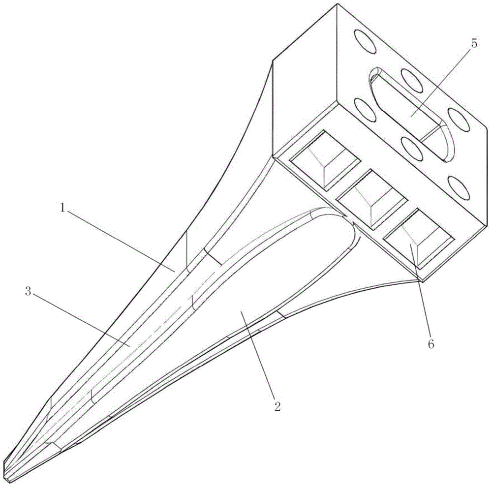
[0022] see figure 1 As shown, one embodiment of the present invention is a crushing tooth, which is installed on the vibrating arm 9 of the crushing hammer. , the end surface of the conical head is square; the middle part of the symmetrical sides of the central carcass 1 is provided with ribs 2 integrally formed with the central carcass 1; the two sides of the ribs 2 are respectively connected with the central tire The adjacent edges of the body 1 form a guide gro...


PUM


Abstract

The embodiment of the invention discloses a breaking tooth which is arranged on a vibration arm of a breaking hammer. The breaking tooth is characterized by comprising a central mold body which is of a rectangular pyramid shape, and the end surface of the pyramid tip is square; rib bodies integrated with the central mold body are arranged at the middle parts of two symmetrical side surfaces of the central mold body, and two sides of the rib body and an edge adjacent to the central mold body form a guide groove. According to the breaking tooth, the rib bodies are additionally arranged on the central mold body, the overall strength and the rigidity of the breaking tooth are improved, and the breaking tooth cannot be easily broken off; soil dust on an action area between the breaking tooth and rock soil can be guided out by the guide groove, the driving resistance of the breaking tooth can be reduced, the dusts can be prevented from bonding on the breaking tooth to influence the sharpness of the breaking tooth, and the power performance and the breaking efficiency of the breaking tooth can be effectively improved.

Description

technical field [0001] The invention relates to the field of rock and soil crushing mechanical equipment, in particular to a crushing tooth matched with a vibrating crushing hammer. Background technique [0002] At present, the crushing teeth matched with the vibrating hammer generally adopt a conventional drill rod structure, and its mechanical properties are determined by its own material. However, the technology of improving its mechanical properties by improving its own structure is often ignored. Due to the limitation of its own structure, the soil and dust in the action area between the crushing teeth and the rock and soil cannot be reasonably discharged, resulting in an increase in resistance to entry into the soil, affecting the dynamic performance and crushing efficiency of the crushing teeth, and also accelerating the Wear of the crushing teeth; in addition, when the crushing teeth are installed, pin shafts are generally used for positioning and fixing. However, th...

Claims


Application Information

Patent Timeline
Patent Type & Authority Applications(China)
IPC IPC(8): B02C13/28
CPCB02C19/16E02F5/30
Inventor 张桂添
Owner 张桂添
Why Eureka
Try Eureka