
Air conditioner air supply angle control method and control system

A technology of air supply angle and control method, applied in the field of control method and control system of air supply angle of air conditioner, to achieve the effect of accelerating the diffusion of warm air, reducing air volume, and reducing the output of air conditioning capacity

Active Publication Date: 2017-08-15
GD MIDEA AIR-CONDITIONING EQUIP CO LTD
View PDF8 Cites 0 Cited by
  • Summary
  • Abstract
  • Description
  • Claims
  • Application Information

AI Technical Summary

Problems solved by technology

[0004] In view of this, the object of the present invention is firstly to provide a method for controlling the air supply angle of an air conditioner, so as to solve the drawbacks of the existing air supply angle adjustment methods, and achieve an adaptive temperature field and wind speed field distribution, thereby improving user experience. comfort

Method used


Image

  • Air conditioner air supply angle control method and control system
  • Air conditioner air supply angle control method and control system
  • Air conditioner air supply angle control method and control system

Examples


Embodiment Construction

[0020] In order to make the object, technical solution and advantages of the present invention clearer, the present invention will be further described in detail below in conjunction with the accompanying drawings and embodiments. It should be understood that the specific embodiments described here are only used to explain the present invention, not to limit the present invention.

[0021] The up and down swing range of the air guide device of the air conditioner is as follows: figure 1 shown. The angle A between the air guiding device 1 and the vertical line a-b is the maximum angle Amax when the air guiding device is at the top, the minimum angle Amin when it is at the bottom, and A0 when it is at the maximum wind outlet angle.

[0022] figure 2 It is a schematic diagram of the relationship between the air volume of the air conditioner and the movement angle of the air guiding device. It can be seen from the figure that the air volume of the air conditioner is the largest...


PUM


Abstract

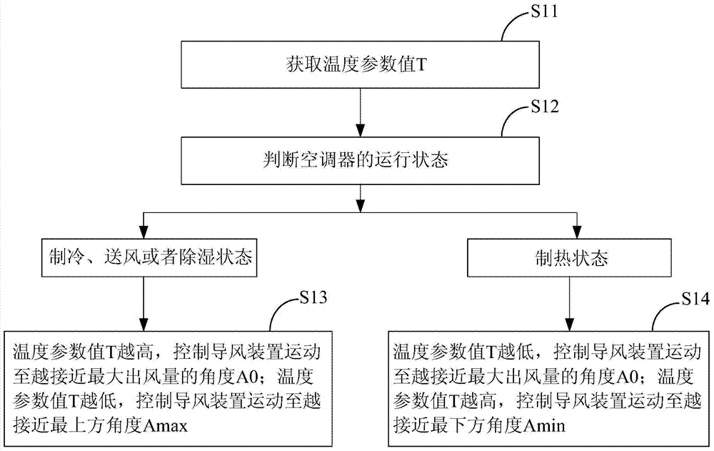
The invention belongs to the field of household air-conditioners and particularly relates to a control method for an air supply angle of the air-conditioner and a control system. Room air speed distribution is controlled according to an obtained temperature parameter value, for instance, in the refrigerating state, or the air supply state or the dehumidifying state, the higher the indoor temperature is, the more approximate to the maximum air output angle an air guide device is, the temperature in a room can be lowered as soon as possible, the cooling degree is increased, or dehumidifying is carried out; after the indoor temperature is lowered, the air guide device moves upwards, the air volume is reduced, and the cooling degree brought by air is reduced so as to solve the problem that the room temperature is low. In the heating state, the lower the indoor temperature is, and the closer the air guide device moves to the maximum air outlet angle, so that spread of warm air is accelerated; the higher the indoor temperature is, the closer the air guide device moves to the bottommost angle so as to reduce air output, and the warm air can be blown towards the ground. According to the method, the position of the air guide device is controlled through the obtained temperature parameter value, a temperature field and an air speed field in the room can be adjusted in a coordinated mode, and the use comfort of users is improved.

Description

technical field [0001] The invention belongs to the field of household air conditioners, and in particular relates to a method and a control system for controlling the air supply angle of an air conditioner. Background technique [0002] For a long time, the air supply angle adjustment methods of the horizontal air guide device of the indoor unit of the air conditioner are only the default angle after power-on, swinging back and forth according to the upper and lower limit angles, and manual adjustment of the air supply angle of the horizontal air guide device by the user. However, the room temperature undergoes different changes from when the user turns on the air conditioner to when the air conditioner is turned off. The traditional air supply angle does not take into account the impact of changes in the temperature and speed of the air supply during the use of the air conditioner on user comfort. [0003] Taking air conditioner cooling in summer as an example, the indoor ...

Claims


Application Information

Patent Timeline
Patent Type & Authority Patents(China)
IPC IPC(8): F24F11/00
CPCF24F11/30F24F2110/10F24F2140/40
Inventor 梁顺标岳宝
Owner GD MIDEA AIR-CONDITIONING EQUIP CO LTD
Learn More