A control method for a steam turbine unit driven by a boiler
A technology for a steam turbine unit and a control method, which is applied to engine components, machines/engines, and mechanical equipment, etc., can solve problems such as reduced economy and reduced operating efficiency, and achieve improved operating economy, reduced plant power consumption, and reduced energy. Effects of Transform Steps
- Summary
- Abstract
- Description
- Claims
- Application Information
AI Technical Summary
Problems solved by technology
Method used
Image
Examples
Embodiment 1
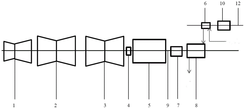
[0047] Such as figure 1 As shown, the hydraulic planetary gear compound transmission device 7 in this embodiment is an RWE type hydraulic planetary gear transmission compound device, but this embodiment can also use an RW type hydraulic planetary gear compound transmission device without affecting Implementation of this embodiment. The steam turbine set driven by the boiler in this embodiment is composed of a steam turbine high and medium pressure combined cylinder 1, a first steam turbine low pressure cylinder 2, a second steam turbine pneumatic cylinder 3, a steam turbine turning device 4, a generator 5, a feed water front pump 6, a hydraulic planetary The compound gear transmission device 7 and the water feed pump 8 are sequentially connected in series through the main shaft 9 of the turbogenerator set, the feed water prepump 6 is connected to the water supply pipe, and the outlet of the feed water prepump 6 is connected to the inlet of the feed water pump 8, as figure 1 T...
Embodiment 2
[0052] Such as image 3 As shown, the hydraulic planetary gear compound transmission device 7 in this embodiment is a RW type hydraulic planetary gear transmission compound device, but this embodiment can also use an RWE type hydraulic planetary gear compound transmission device without affecting Implementation of this embodiment. The steam turbine set driven by the boiler in this embodiment consists of a steam turbine high and medium pressure combined cylinder 1, a first steam turbine low pressure cylinder 2, a second steam turbine pneumatic cylinder 3, a steam turbine barring device 4, a generator 5, a hydraulic planetary gear compound transmission device 7 and The feed water pump 8 is sequentially connected in series through the main shaft 9 of the turbogenerator set. This embodiment is also provided with a feedwater prepump motor 10 and a feedwater prepump 6 connected sequentially through the shaft system 12 of the feedwater prepump group, the feedwater prepump 6 is conne...
Embodiment 3
[0057] Adopt the device of embodiment 1, as Figure 8 As shown, the controller controls the feed water flow as follows:
[0058] 1) Read the water supply pressure P under the target load of the unit 1 ,
[0059] 2) will P 1 and measured water pressure value P 0 , to compare in the controller;
[0060] 3) If P 1 0 If the comparison result is "Yes", the controller sends a signal to the hydraulic planetary gear compound transmission to increase the transmission ratio of the hydraulic planetary gear compound transmission by X 1 , P 0 increase, and then the measured water supply pressure value P 0 feedback to the controller;
[0061] 4) If P 10 If the comparison result is "No", the controller sends a signal to the hydraulic planetary gear compound transmission to reduce the transmission ratio of the hydraulic planetary gear compound transmission by X 1 , P 0 Decrease, then the measured water supply pressure value P 0 feedback to the controller;
[0062] 5) Repeat steps...
PUM
 Abstract
Description
Claims
Application Information
 - R&D
- Intellectual Property
- Life Sciences
- Materials
- Tech Scout
- Unparalleled Data Quality
- Higher Quality Content
- 60% Fewer Hallucinations
Browse by: Latest US Patents, China's latest patents, Technical Efficacy Thesaurus, Application Domain, Technology Topic, Popular Technical Reports.
© 2025 PatSnap. All rights reserved.Legal|Privacy policy|Modern Slavery Act Transparency Statement|Sitemap|About US| Contact US: help@patsnap.com


