
A method for estimating three-dimensional deformation of mine surface with high spatio-temporal resolution

A technology with spatial and temporal resolution and three-dimensional deformation, applied in instruments, complex mathematical operations, measurement devices, etc., can solve the problem of difficult to obtain time-series deformation results of mining areas, large changes in surface cover, and difficult to obtain highly nonlinear mining surface. Time series deformation results and other issues

Active Publication Date: 2020-06-30
CENT SOUTH UNIV
View PDF7 Cites 0 Cited by
  • Summary
  • Abstract
  • Description
  • Claims
  • Application Information

AI Technical Summary

Problems solved by technology

2) Since most of the mining areas are located in rural areas and suburbs, the surface cover usually changes greatly, and the surface deformation rate is relatively fast, making it difficult to obtain time-series deformation results of the mining area based on single-track InSAR data
Especially when there is a time gap in the single-track data set, it will be difficult to obtain highly nonlinear time-series deformation results of the mining area using the traditional least squares-based algorithm

Method used


Image

  • A method for estimating three-dimensional deformation of mine surface with high spatio-temporal resolution
  • A method for estimating three-dimensional deformation of mine surface with high spatio-temporal resolution
  • A method for estimating three-dimensional deformation of mine surface with high spatio-temporal resolution

Examples


Embodiment Construction

[0059] The present invention will be further described below in conjunction with examples.

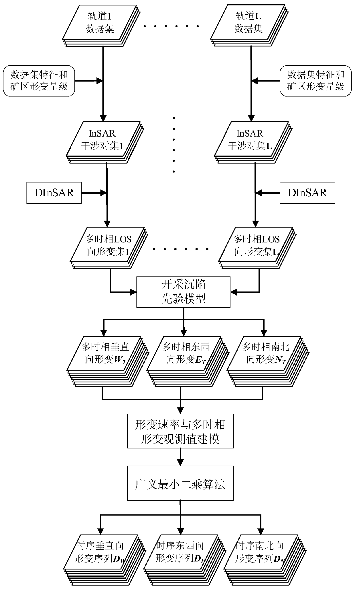
[0060] Such as figure 1 As shown, the embodiment of the present invention provides a method for more accurately predicting the surface deformation energy of the mining area, including the following steps:

[0061] S1: Based on the SAR images acquired by each orbit, a set of interferometric InSAR interferometric pairs is formed.

[0062]Among them, the SAR images of L orbits form L SAR image sets to cover the mining area to be monitored, and L is a positive integer greater than or equal to 2. The number of each SAR image set is expressed as: M 1 , M 2 ,...,M L , the total number of SAR images is M+1, that is, M+1=M 1 +...M j …+M L .

[0063] Based on the SAR image set of each orbit, the InSAR interference pair set corresponding to each orbit is generated, and the number of InSAR interference pairs in each InSAR interference pair set is: G 1 ,G 2 ,...,G L , the total number of...


PUM


Abstract

The present invention discloses a three-dimensional deformation estimation method for high temporal and spatial resolution at a mining area surface. The method comprises: separately forming each orbital SAR data into a set of InSAR interference pairs; then obtaining a monitoring data set from one-dimensional radar line of sight to multi-temporal deformation at the mining area surface; jointly solving the monitoring data set from one-dimensional radar line of sight to multi-temporal deformation at the mining area surface and a prior model for a linear proportional relationship between horizontal movement caused by mining subsidence and subsidence gradient to obtain a three-dimensional multi-temporal deformation observation field along vertical, west-east and north-south directions of the mining area surface; establishing an observation equation for a three-dimensional deformation rate during time-adjacent SAR images in a multi-track SAR image data set and the three-dimensional multi-temporal deformation observation field; and solving the observation equation to obtain a three-dimensional deformation of high temporal and spatial resolution at the mining area surface. The present invention overcomes the stringent requirements and limitations for observation measurement and observation geometry in a traditional InSAR three-dimensional deformation estimation method; the time resolution of a monitoring result is obviously improved, and a more accurate result is obtained.

Description

technical field [0001] The invention belongs to the technical field of mining area measurement, and in particular relates to a method for estimating three-dimensional deformation of mining area surface with high temporal and spatial resolution based on a priori model of mining subsidence. Background technique [0002] The three-dimensional deformation monitoring of mining area surface with high temporal and spatial resolution plays an important role in understanding the dynamic mechanism of mining subsidence in mining area, disaster prevention and accurate assessment in mining area. Synthetic aperture radar interferometry (Interferometric Synthetic Aperture Radar, InSAR) technology plays a huge role in the monitoring and prediction of surface deformation in mining areas due to its high spatial resolution, high precision, and no interference from cloud and rain. However, the deformation monitored by InSAR technology is the one-dimensional projection of the real three-dimensio...

Claims


Application Information

Patent Timeline
Patent Type & Authority Patents(China)
IPC IPC(8): G01S13/90G06F17/11
Inventor 杨泽发王跃东李志伟朱建军王琪洁
Owner CENT SOUTH UNIV
Learn More