
Chip removing device for metal processing lathe

A metal processing and cleaning device technology, applied in metal processing equipment, metal processing mechanical parts, manufacturing tools, etc., can solve the problems of easily scratching the operator's skin, affecting the quality of metal processing, etc., to avoid processing quality and ensure safety. Effect

Active Publication Date: 2015-02-25
苏州微米光电子科技有限公司
View PDF6 Cites 4 Cited by
  • Summary
  • Abstract
  • Description
  • Claims
  • Application Information

AI Technical Summary

Problems solved by technology

[0002] As people have higher and higher precision requirements for parts and metal processing, they rely more and more on lathe processing. More and more metal debris accumulates on the lathe, which not only affects the quality of metal processing, but also easily scratches the skin of the operator

Method used


Image

  • Chip removing device for metal processing lathe
  • Chip removing device for metal processing lathe
  • Chip removing device for metal processing lathe

Examples


Embodiment Construction

[0018] In order for examiners to better understand the technical features, technical contents and technical effects of the present invention, the accompanying drawings of the present invention will now be described in more detail in conjunction with the embodiments. However, the drawings shown are only for better illustration of the technical solutions of the present invention, not the true scale and optimal configuration of the present invention, so the examiner is requested not to limit the scope of the present invention with respect to the ratio and configuration of the drawings Scope of claims.

[0019] Below in conjunction with accompanying drawing and embodiment the patent of the present invention is further described.

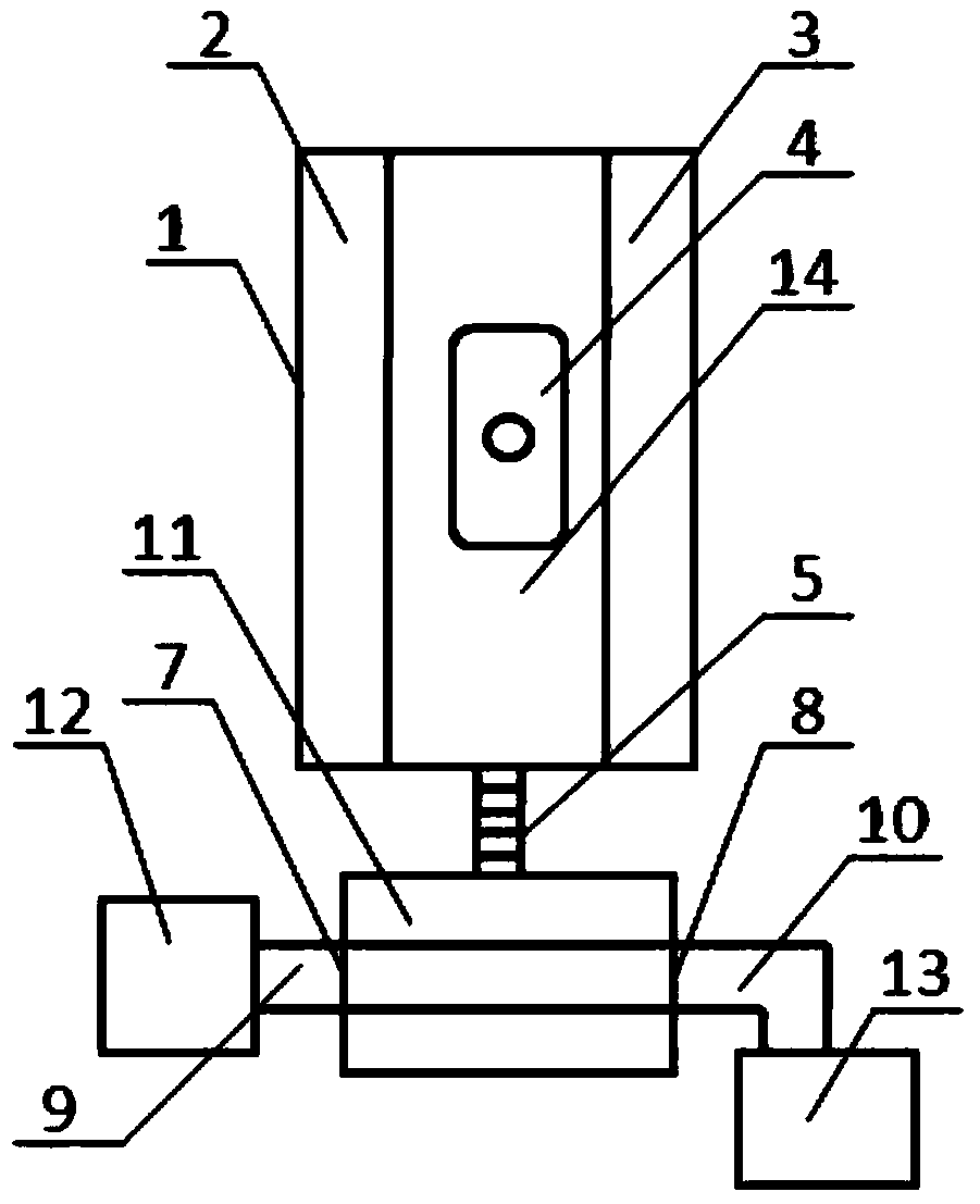
[0020] Such as Figure 1-3 As shown, the present invention includes a groove chamber 14 arranged on the lathe bed 1, the groove chamber 14 is a cuboid structure, and a suction cup 4 is fixedly installed at the bottom of the groove chamber 14, and the su...


PUM


Abstract

The invention discloses a chip removing device for a metal processing lathe. The chip removing device comprises a groove bin room formed in a lathe body, the groove bin room is of a cuboid structure, the bottom of the groove bin room is provided with a suction disc in a fixed mode, the suction disc is connected with a negative pressure generator through a chip removing tube, an air inlet is formed in one end of the negative pressure generator, an air outlet is formed in the other end of the negative pressure generator, the air inlet of the negative pressure generator is connected with a steel cylinder for storing air through an air inlet tube, a shell of the negative pressure generator is provided with a tube hole matched with the chip removing tube, a baffle is arranged at the bottom of the later wall, close to the air inlet, of the tube hole and rotates with a rotating shaft of the baffle as a circle center, an air exhausting hole is formed in the bottom of the lateral wall, close to the air outlet, of the tube hole and connected with an air exhausting device through an air exhausting tube, and a filtering net is arranged at the position of the air exhausting hole. Chips can be synchronously removed in the metal processing process, the processing quality is prevented from being influenced by chip accumulation, and meanwhile the safety of an operator is guaranteed.

Description

technical field [0001] The invention relates to the technical field of metal processing equipment, in particular to a debris cleaning device for a metal processing lathe. Background technique [0002] As people have higher and higher precision requirements for parts and metal processing, they rely more and more on lathe processing. More and more metal debris accumulates on the lathe, which not only affects the quality of metal processing, but also easily scratches the skin of the operator. Contents of the invention [0003] In order to solve the above-mentioned defects and deficiencies in the prior art, the present invention provides a chip cleaning device for metal processing lathes, which can be carried out simultaneously with metal processing, not only automatically removes metal chips generated during the operation of the lathe, but also has a simple structure , easy to operate. [0004] In order to solve the above technical problems, the present invention provides a...

Claims


Application Information

Patent Timeline
Patent Type & Authority Applications(China)
IPC IPC(8): B23Q11/00B25B25/00
CPCB23Q11/0046
Inventor 周天毫
Owner 苏州微米光电子科技有限公司
Learn More