High-voltage cabinet busbar joint temperature and current monitoring and protecting system
A busbar connector and current monitoring technology, applied in electrical components, circuit devices, fire alarms that rely on the effect of smoke/gas, etc., can solve problems such as inability to perform remote monitoring, emergency situations cannot be handled in time, etc., and achieve network transmission. The effect of fast speed, fast communication speed and high degree of intelligence
- Summary
- Abstract
- Description
- Claims
- Application Information
AI Technical Summary
Problems solved by technology
Method used
Image
Examples
Embodiment 1
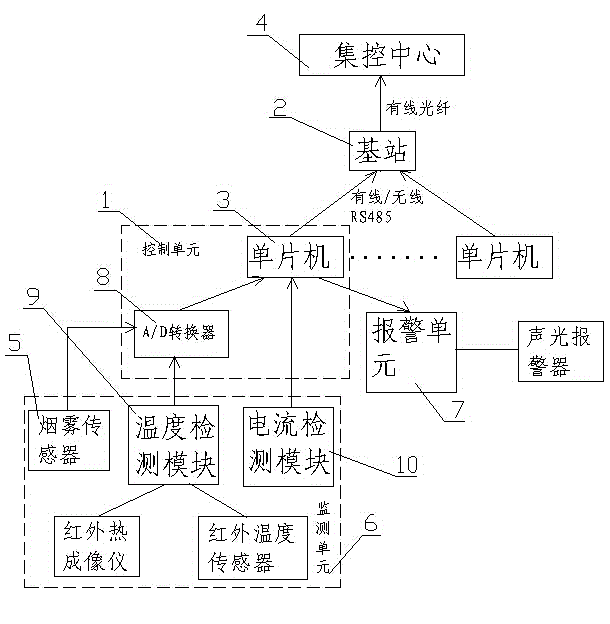
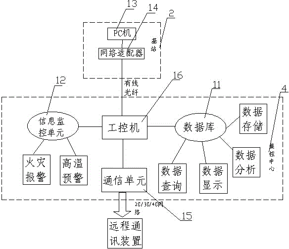
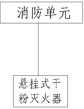
[0031] Such as figure 1 , figure 2 and image 3As shown: the present invention provides a high-voltage cabinet bus joint temperature and current monitoring and protection system, including a monitoring unit 6, a control unit 1, a fire fighting unit, an alarm unit 7, a base station 2 and a centralized control center 4, the monitoring unit 6, Control unit 1, base station 2 and centralized control center 4 are connected in sequence, and described monitoring unit 6 comprises temperature monitoring module 9 and current monitoring module 10, and described control unit 1 comprises A / D converter 8, single-chip microcomputer 3, and described fire-fighting unit Including an automatic fire extinguisher, the control unit 1 is connected to the base station 2 through RS485, and the base station 2 is connected to the central control center 4 through wired optical fiber. The temperature and current of the bus joints in the high-voltage cabinet and the temperature in the high-voltage cabine...
Embodiment 2
[0035] Such as figure 1 , figure 2 and image 3 As shown: the present invention also provides a high-voltage cabinet bus joint temperature and current monitoring and protection system, including a monitoring unit 6, a control unit 1, a fire fighting unit, an alarm unit 7, a base station 2 and a centralized control center 4, and the monitoring unit 6 , control unit 1, base station 2 and centralized control center 4 are connected in sequence, and described monitoring unit 6 comprises temperature monitoring module 9 and current monitoring module 10, and described control unit 1 comprises A / D converter 8, single-chip microcomputer 3, and described fire-fighting The unit includes an automatic fire extinguisher, the control unit 1 is connected to the base station 2 through RS485, and the base station 2 is connected to the centralized control center 4 through wired optical fiber.
[0036] The automatic fire extinguisher adopts a suspended dry powder fire extinguisher, which can au...
Embodiment 3
[0039] Such as figure 1 , figure 2 and image 3 As shown: the present invention also provides a high-voltage cabinet bus joint temperature and current monitoring and protection system, including a monitoring unit 6, a control unit 1, a fire fighting unit, an alarm unit 7, a base station 2 and a centralized control center 4, and the monitoring unit 6 , control unit 1, base station 2 and centralized control center 4 are connected in sequence, and described monitoring unit 6 comprises temperature monitoring module 9 and current monitoring module 10, and described control unit 1 comprises A / D converter 8, single-chip microcomputer 3, and described fire-fighting The unit includes an automatic fire extinguisher, the control unit 1 is connected to the base station 2 through RS485, and the base station 2 is connected to the centralized control center 4 through wired optical fiber.
[0040] The base station 2 realizes wireless connection with the control unit 1 through 485 to WIFI t...
PUM
 Abstract
Description
Claims
Application Information
 - R&D
- Intellectual Property
- Life Sciences
- Materials
- Tech Scout
- Unparalleled Data Quality
- Higher Quality Content
- 60% Fewer Hallucinations
Browse by: Latest US Patents, China's latest patents, Technical Efficacy Thesaurus, Application Domain, Technology Topic, Popular Technical Reports.
© 2025 PatSnap. All rights reserved.Legal|Privacy policy|Modern Slavery Act Transparency Statement|Sitemap|About US| Contact US: help@patsnap.com


