
Method for evaluating high sound intensity characteristics of sound intensity measuring instrument

An evaluation method, measuring instrument technology, applied in the measurement of ultrasonic/sonic/infrasonic waves, measuring devices, instruments, etc.

Active Publication Date: 2015-02-11
BEIJING AEROSPACE INST FOR METROLOGY & MEASUREMENT TECH +1
View PDF3 Cites 9 Cited by
  • Summary
  • Abstract
  • Description
  • Claims
  • Application Information

AI Technical Summary

Problems solved by technology

[0005] The above calibration method requires the experimental conditions of an anechoic room, the sound intensity level of the sound source is less than 110dB, and it is impossible to calibrate the sound intensity measuring instrument whose dynamic range upper limit reaches 150dB sound intensity level
[0006] At present, sound intensity measurements at home and abroad are mainly carried out in large traveling wave tubes and anechoic chambers, focusing on the frequency response calibration of sound intensity levels. Generally, sound intensity levels are less than 110dB, and the dynamic range upper limit and sound intensity of sound intensity levels in a wide dynamic range The evaluation method of level deviation calibration is always a missing item

Method used


Image

  • Method for evaluating high sound intensity characteristics of sound intensity measuring instrument
  • Method for evaluating high sound intensity characteristics of sound intensity measuring instrument
  • Method for evaluating high sound intensity characteristics of sound intensity measuring instrument

Examples


Embodiment 1

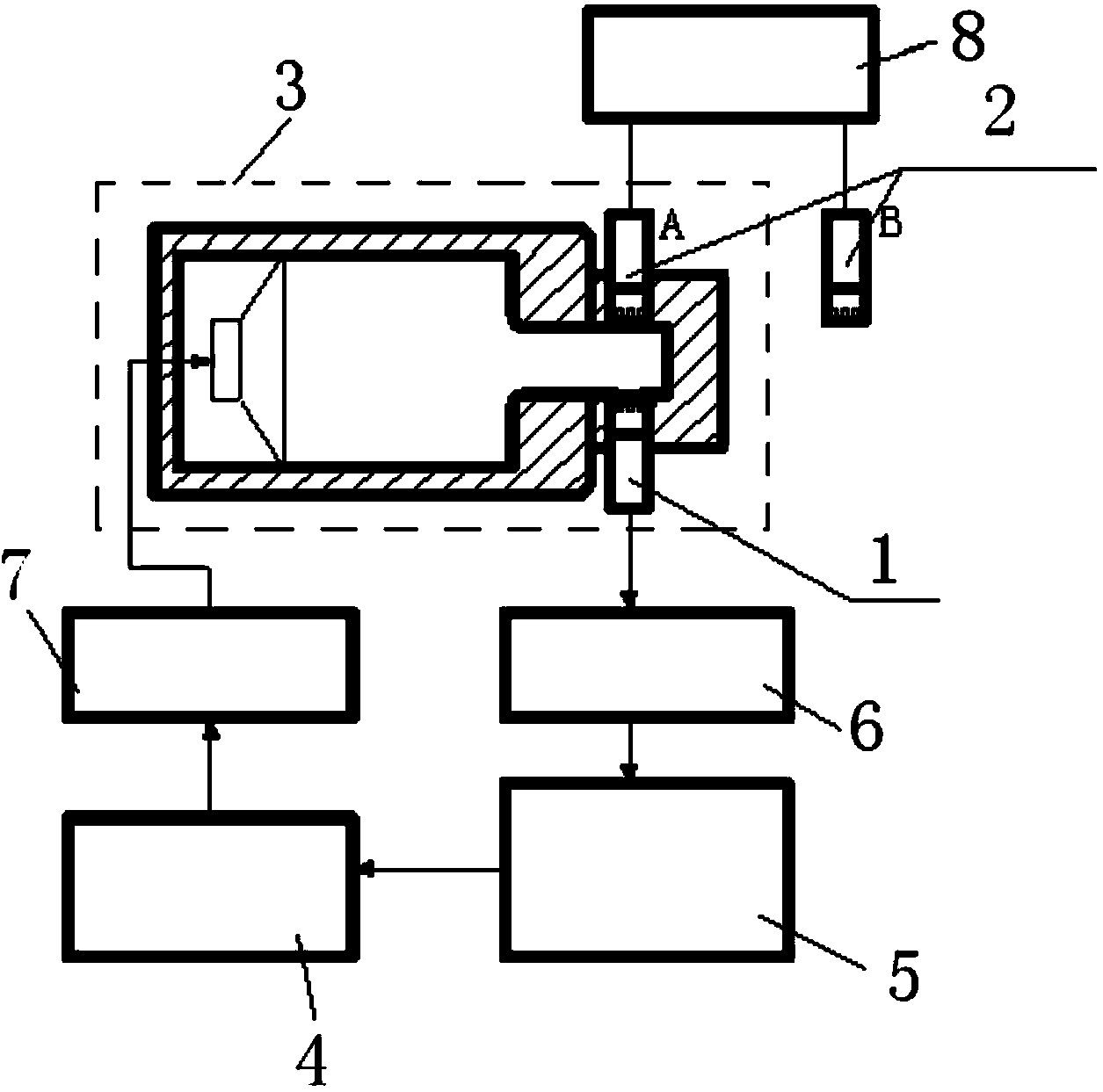
[0045] Such as figure 2 As shown, a method for evaluating the high sound intensity characteristics of a sound intensity measuring instrument according to the present invention is used for the evaluation of the upper limit of the dynamic range of the sound intensity level of the sound intensity measuring instrument. The sound intensity probe of the sound intensity measuring instrument has Two sound intensity probe microphones 2, both of which are connected to the sound intensity analyzer 8; one sound intensity probe microphone 2A of the sound intensity measuring instrument and the high sound pressure standard microphone 1 are axially symmetrically installed in the sound intensity level calibration On the device 3; the method comprises the steps of:

[0046] (a) The signal of a sound intensity probe microphone 2A is output to the sound intensity analyzer 8, and the sound intensity analyzer 8 outputs the sound pressure level measured to the data acquisition analyzer 5;

[0047]...

Embodiment 2

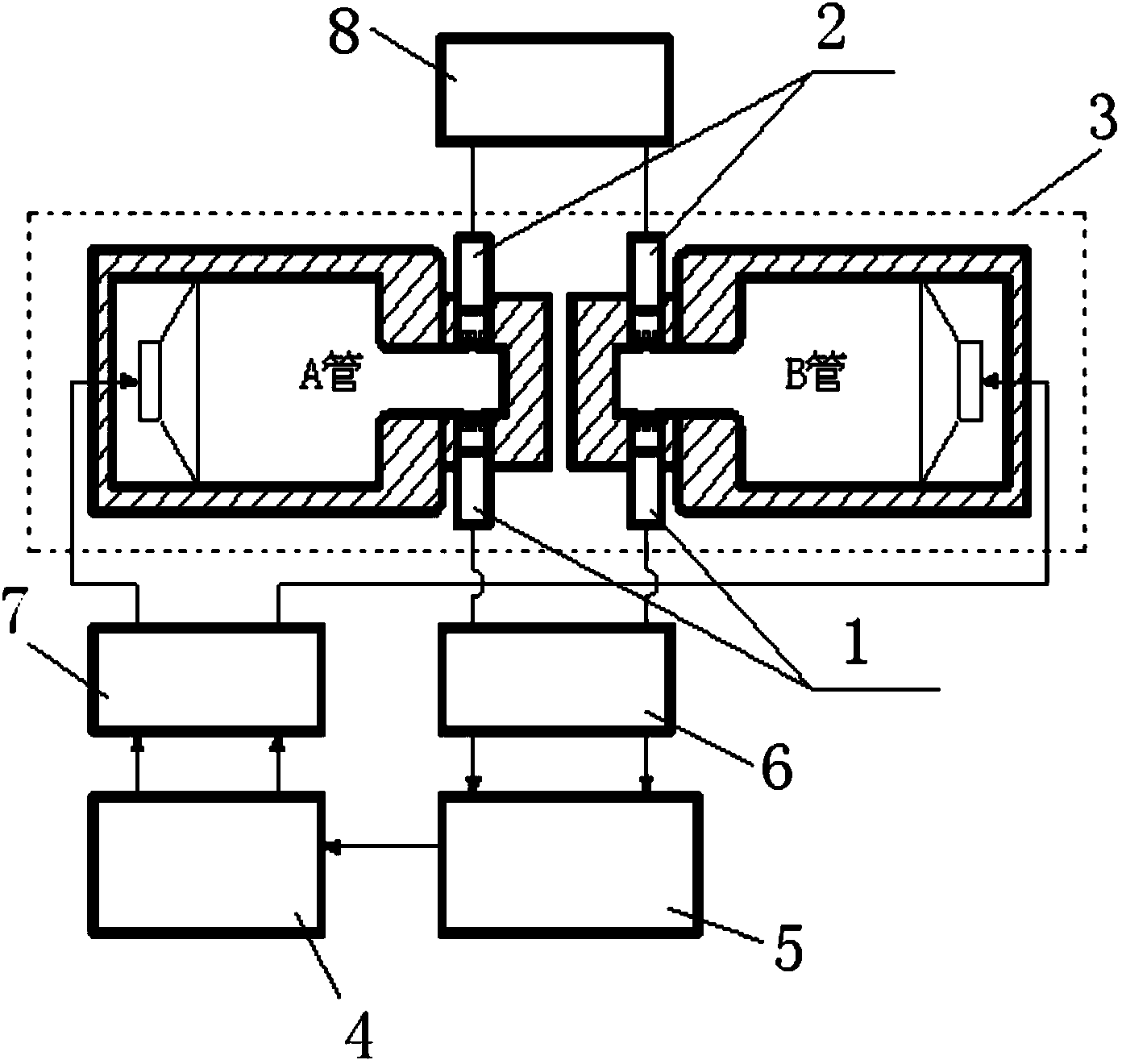
[0067] Such as image 3 As shown, a method for evaluating the high sound intensity characteristics of a sound intensity measuring instrument according to the present invention is used for sound intensity level deviation calibration, and the sound intensity probe of the sound intensity measuring instrument to be calibrated has two sound intensity probe microphones 2, The two sound intensity probe microphones 2 are connected to the sound intensity analyzer 8; the two sound intensity probe microphones 2A, 2B of the sound intensity measuring instrument and the two high sound pressure standard microphones 1 are axially symmetrically installed on the sound intensity level calibration device 3; The method comprises the steps of:

[0068] (a) the nominal spacing of two sound intensity probe microphones 2A, 2B of the sound intensity measuring instrument is set to be 50mm; the sound intensity analyzer 8 outputs the sound pressure level measured to the data acquisition analyzer 5;

[00...


PUM


Abstract

The invention provides a method for evaluating high sound intensity characteristics of a sound intensity measuring instrument. The method is used for evaluating sound intensity level dynamic range upper limit of the sound intensity measuring instrument, and calibrating sound intensity level deviation; a sound intensity probe of the to-be-calibrated sound intensity measuring instrument is provided with two sound intensity probe microphones; the two sound intensity probe microphones are both connected with a sound intensity analysis meter; the intensity probe microphones of the sound intensity measuring instrument and a high sound pressure standard microphone are arranged on a sound intensity level calibration device in axial symmetry. Through the method, the standard sound intensity level is simulated through a standing wave tube sound wave generation technology based on the double resonance sound wave amplitude-phase control principle; the evaluation of sound intensity measuring instrument calibration with measurement range of 100-150dB can be realized.

Description

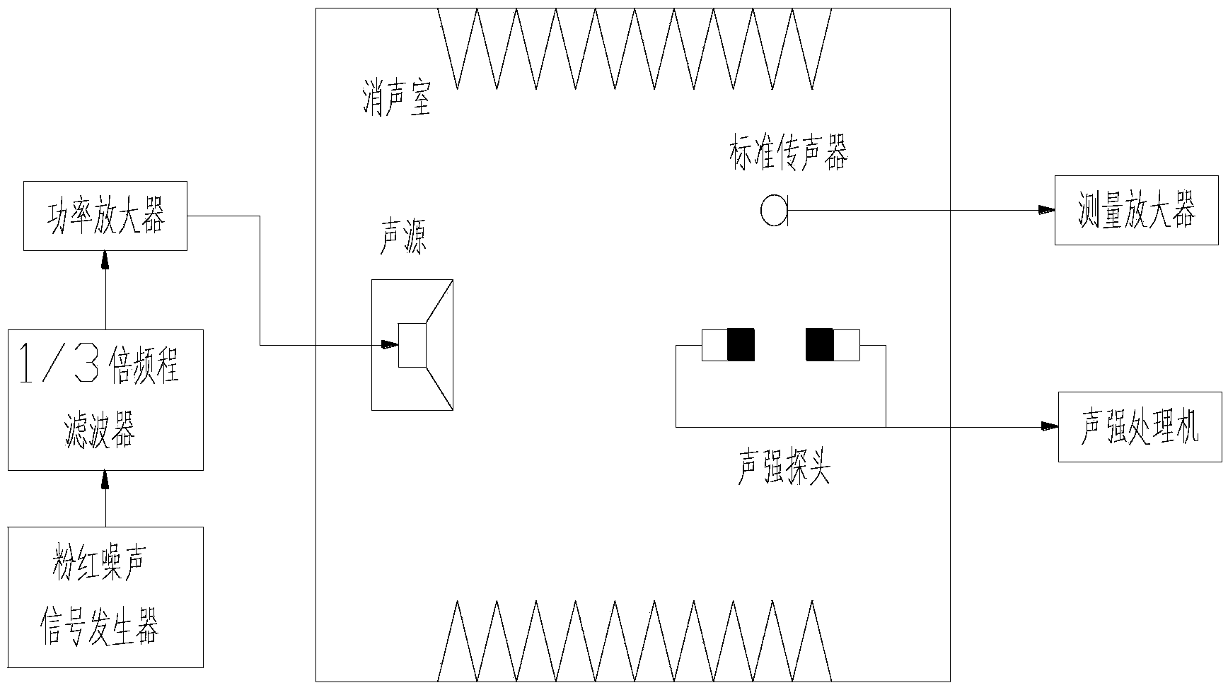
technical field [0001] The invention belongs to the technical field of acoustic measurement, and in particular relates to a method for evaluating the high sound intensity characteristics of a sound intensity measuring instrument. Background technique [0002] According to the requirements in "JJG 992-2004 Verification Regulations for Sound Intensity Measuring Instruments", the sound intensity measuring instrument to be inspected should perform "sound pressure frequency response and sound intensity frequency response calibration" according to the method described in Article 7.3.6 of the regulations, The experimental setup for this method is figure 1 shown. [0003] In the anechoic chamber, sound-absorbing materials are attached to the wall to form a free sound field with almost zero sound reflection. The sound intensity probe is placed in the free sound field, and the standard microphone is placed at a distance of 40-50mm from the sound intensity probe to monitor the sound f...

Claims


Application Information

Patent Timeline
Patent Type & Authority Applications(China)
IPC IPC(8): G01H17/00
Inventor 闫磊杨晓伟朱刚刘鑫缪寅宵裴雅鹏王小三
Owner BEIJING AEROSPACE INST FOR METROLOGY & MEASUREMENT TECH
Learn More