Welding method of the four-way switching valve and the fixing screw of the four-way switching valve

A four-way switching valve and welding method technology, which is applied to multi-way valves, welding equipment, valve devices, etc., can solve the problems of increasing the number of parts, troublesome assembly operations, and increasing costs, and achieves easy assembly operations, easy welding operations, and easy welding. The effect of preventing loosening

Inactive Publication Date: 2016-09-07
SAGINOMIYA SEISAKUSHO INC
View PDF4 Cites 0 Cited by
  • Summary
  • Abstract
  • Description
  • Claims
  • Application Information

AI Technical Summary

Problems solved by technology

In order to improve the durability of the piston device, it is necessary to prevent the rotation of such bolts, but if riveted plates and plate parts are used, there are problems that the number of parts increases, the assembly work is troublesome, and the cost increases

Method used


Image

  • Welding method of the four-way switching valve and the fixing screw of the four-way switching valve
  • Welding method of the four-way switching valve and the fixing screw of the four-way switching valve
  • Welding method of the four-way switching valve and the fixing screw of the four-way switching valve

Examples


Embodiment Construction

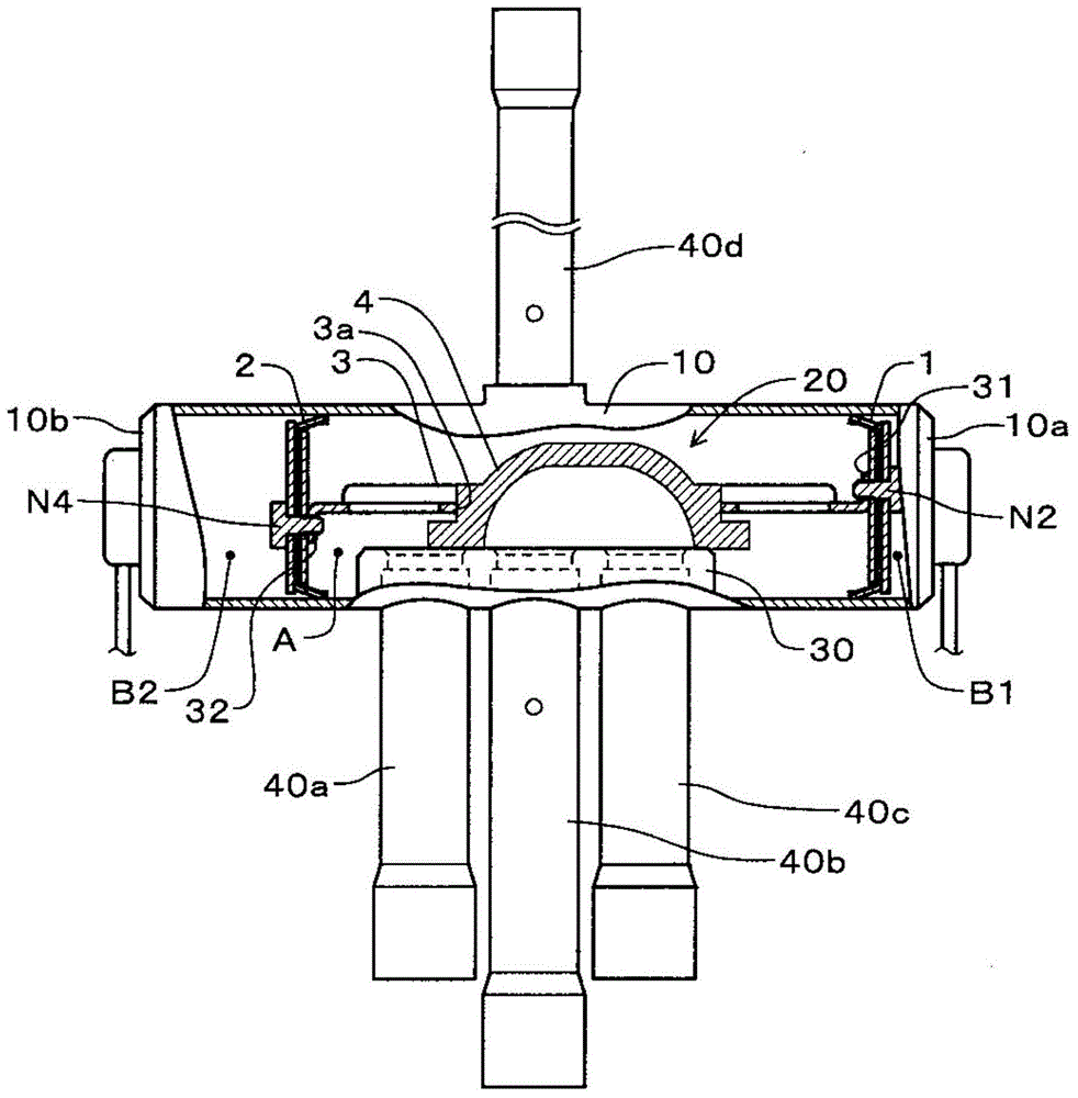
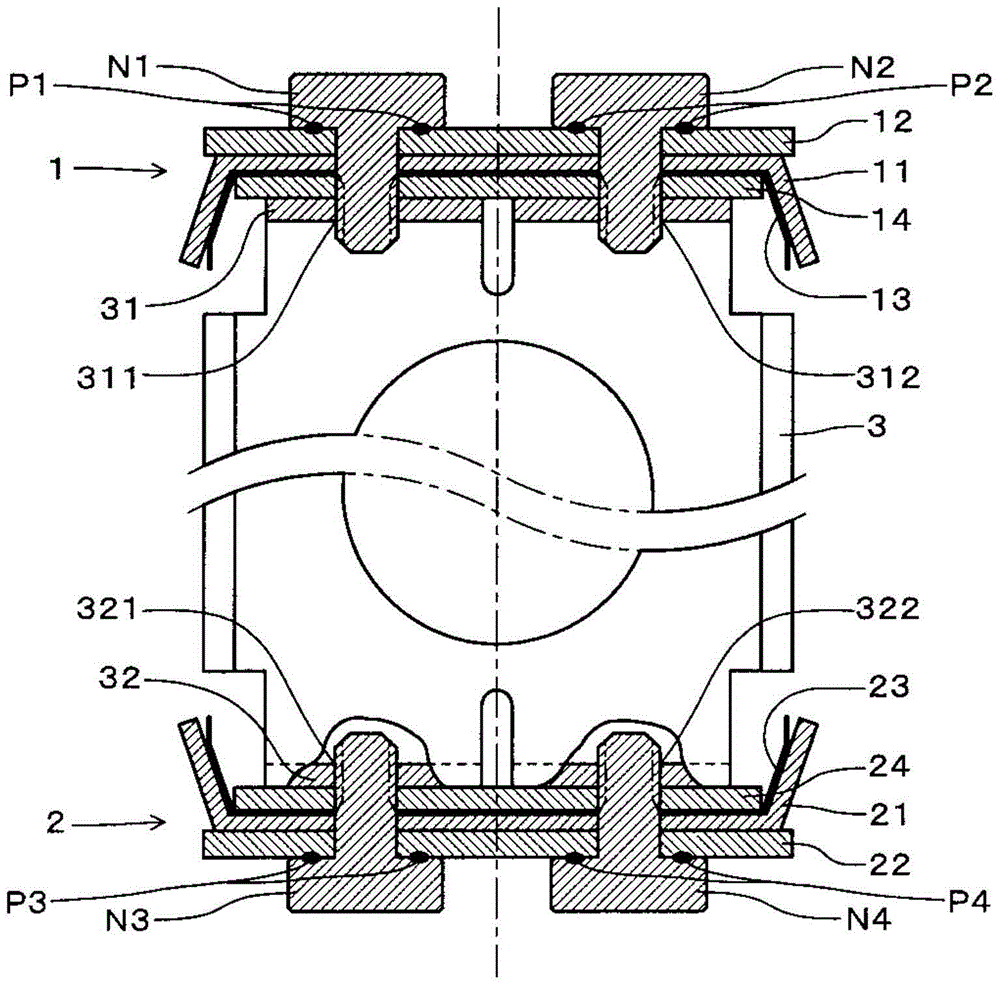
[0024] Next, embodiments of the present invention will be described. figure 1 It is a partially cutaway side view of the four-way switching valve of the embodiment. The four-way switching valve of this embodiment includes: a valve case 10 constituting a cylindrical main valve chamber A, first and second sub-valve chambers B1, B2; a piston valve 20 accommodated in the valve case 10; Valve seat 30 in valve housing 10 . The piston valve 20 is composed of a first piston 1 , a second piston 2 , a stainless steel connection fitting 3 , and a bowl-shaped valve body 4 . The first and second pistons 1 and 2 are respectively attached to both ends of the joint fitting 3 , and the valve body 4 is fitted into a fitting hole 3 a in the center of the joint fitting 3 to be held by the joint fitting 3 .

[0025] The first and second pistons 1, 2 divide the inside of the valve casing 10 into a main valve chamber A in the center and two sub-valve chambers B1, B2 on both sides thereof. The fou...


PUM


Abstract

PROBLEM TO BE SOLVED: To provide a four-way selector valve such that a lockscrew for fixing a piston to coupling metal fittings is securely prevented from being loosened, the number of components is decreased, and trouble in manufacture is saved.SOLUTION: A piston valve is accommodated in a valve housing. The piston valve comprises first and second pistons 1 and 2, coupling metal fittings 3, and a valve body. The piston 1 comprises a packing 11, a guide plate 12, a toothed lock spring 13, and a reinforcing plate 14. The piston 2 comprises a packing 21, a guide plate 22, a toothed lock spring 23, and a reinforcing plate 24. The piston 1 is fixed to a vertical plate 31 of the coupling metal fittings 3 with lockscrews N1, N2. The piston 2 is fixed to a vertical plate 32 of the coupling metal fittings 3 with lockscrews N3, N4. Molten layers P1, P2 are formed by resistance welding at a contact place between the lockscrew N1 and the guide plate 12 and at a contact place between the lockscrew N2 and the guide plate 12. Molten layers P3, P4 are formed by resistance welding at a contact place between the lockscrew N3 and the guide plate 22 and at a contact place between the lockscrew N4 and the guide plate 22.

Description

technical field [0001] The present invention relates to a four-way switching valve having a piston valve having pistons at both ends of a connecting fitting holding a bowl-shaped valve body, and a valve case housing the piston valve, and the piston valve is moved by fluid pressure. Switching the flow path relates in detail to the structure of the piston valve and the welding method of its fixing screws. Background technique [0002] Conventionally, as a piston valve of such a four-way switching valve, there is, for example, a piston device disclosed in JP 2009-144880 A (Patent Document 1). In this patent document 1, in the conventional piston device, the auxiliary spring and the spacer are clamped by the clamping plate, and the plate member is abutted against and fixed by riveting, thereby assembling the single piston. Then, two of the piston units are respectively fastened to the ends of the connecting plate (connecting fitting) by bolts (fixing screws). In addition, as a...

Claims


Application Information

Patent Timeline
Patent Type & Authority Patents(China)
IPC IPC(8): F16K11/06B23K11/00
CPCB23K11/00F16K11/0655
Inventor 村田雅弘木村宏光
Owner SAGINOMIYA SEISAKUSHO INC
Why Eureka
Try Eureka