


Quick Research
Generate reliable direction feasibility study reports for your R&D in just a few steps.

Technical Q&A
Discover and master advanced knowledge NOW. Basics, ideas, possibilities, all at once.

Find Solutions
As an expert in R&D theories, this can generate solutions to your technical problems instantly.

Evaluate Feasibility
Analyze your overall solution with one click, know your potential R&D risks in advance.

Monitor Landscape
Get weekly tech updates, stay abreast of the latest tech innovations and key insights.
Apparatus for fixing position of workpiece
A technology of fixing device and workpiece position, applied in workpiece clamping device, positioning device, clamping device, etc., can solve problems such as adverse effects on productivity, poor processing, etc., to reduce the possibility of workpiece shaking, stabilize the position, reduce The effect of the phenomenon of shaking from side to side
- Summary
- Abstract
- Description
- Claims
- Application Information
AI Technical Summary
Problems solved by technology
Method used
Image

Examples
no. 1 example 〉
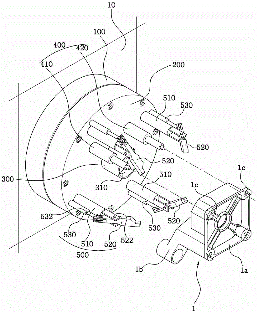
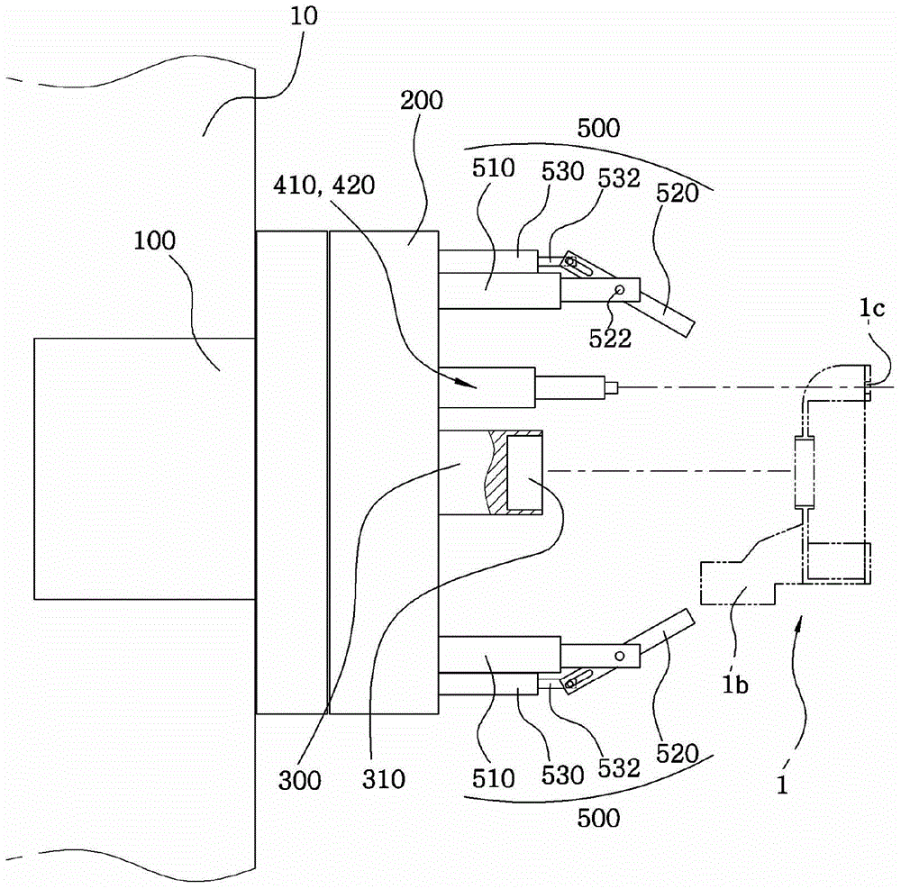
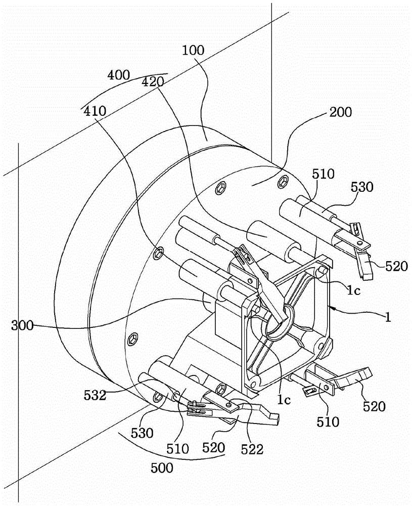
[0059] like figure 1 and figure 2 As shown, the position fixing device in this embodiment includes a rotation driving part 100 , a rotating disk 200 , a mounting rod 400 and a position fixing part 500 .
[0060] The rotary drive unit 100 functions as a drive source for rotating the workpiece 1 by a rotary table 200 to be described later. The rotation driving part 100 is composed of an AC (alternating current) motor or a DC (direct current) motor, and is fixed on the main body 10 .
[0061] As shown in the figure, the rotary drive unit 100 is composed only of a motor, and is directly connected to a rotating disk 200 described later through a motor shaft. Moreover, it may also be indirectly connected to the rotating disk 200 through a separate gear or a power transmission device such as a pulley or a sprocket.
[0062] A rotary disk 200 is connected to the rotary drive unit 100 .
[0063] The rotary table 200 functions as a support body when installing the workpiece 1 , the...
no. 2 example
[0119] Figure 8 to Figure 16 It is a figure which shows another modification of this invention.
[0120] In the second embodiment of the present invention, the workpiece 1 is combined with the first and second mounting rods 410, 420, and the position fixing part 500 is connected to the workpiece 1 for support, so the basic technical concept of realizing the position fixation of the workpiece 1 is consistent with the above-mentioned first One embodiment is the same, but the difference is that the structure of the position fixing part 500 is different.
[0121] The position fixing part 500 in the second embodiment is the same as the first embodiment, and basically includes a protruding rod 510, a support member 520 and a rotation drive member 530, but the implementation of the rotation drive member 530 is different, and the rotation structure of the support member 520 is changed. , In addition, a front and rear driving member 540 is added, so that the support member 520 can mo...
no. 3 example 〉
[0152] Figure 17 to Figure 20 It is a figure which shows still another modification of this invention.
[0153] In the third embodiment of the present invention, in the state where the workpiece 1 is combined with the first and second mounting rods 410, 420, the basic technical concept of making the position fixing part 500 contact the workpiece 1 to fix the position is the same as that of the above-mentioned first embodiment. It is the same as the second embodiment, but the difference is that there is also an anti-deviation member 600 capable of supporting the opposite side of the workpiece 1 to the joint side of the first and second mounting rods 410 , 420 .
[0154] For reference, it is shown in the drawings that the misalignment preventing member 600 is applicable to the structure of the first embodiment, but the misalignment preventing member 600 may also be applicable to the second embodiment.
[0155] The anti-deflection member 600 in the third embodiment prevents the...
PUM
 Abstract
Description
Claims
Application Information
 - R&D Engineer
- R&D Manager
- IP Professional
- Industry Leading Data Capabilities
- Powerful AI technology
- Patent DNA Extraction
Browse by: Latest US Patents, China's latest patents, Technical Efficacy Thesaurus, Application Domain, Technology Topic, Popular Technical Reports.
© 2024 PatSnap. All rights reserved.Legal|Privacy policy|Modern Slavery Act Transparency Statement|Sitemap|About US| Contact US: help@patsnap.com