
Device for molding ceramic core of directionally solidified blade

A ceramic core and directional solidification technology, which is applied in the direction of core, mold composition, mold, etc., can solve problems such as low assembly accuracy, cracks, and failure to remove ceramic cores

Active Publication Date: 2015-02-11
SHENYANG LIMING AERO-ENGINE GROUP CORPORATION
View PDF5 Cites 4 Cited by
  • Summary
  • Abstract
  • Description
  • Claims
  • Application Information

AI Technical Summary

Problems solved by technology

Solve the problems of low assembly accuracy, inconvenient operation, inability to remove the ceramic core, cracks, deformation and poor surface finish

Method used


Image

  • Device for molding ceramic core of directionally solidified blade
  • Device for molding ceramic core of directionally solidified blade
  • Device for molding ceramic core of directionally solidified blade

Examples


Embodiment 1

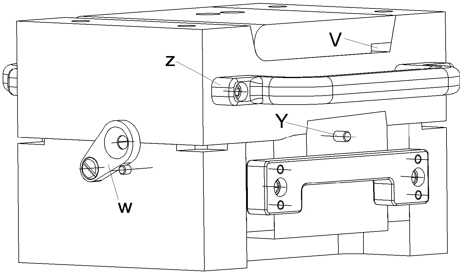
[0029] The directional solidification vane ceramic core forming device has a cuboid structure as a whole, see the attached figure 1 , the material of the directional solidification blade ceramic core forming device is P20, and the overall parting surface is a composite of a plane and a complex curved surface.

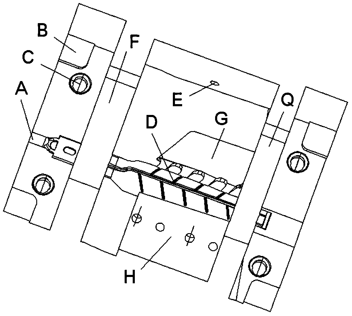
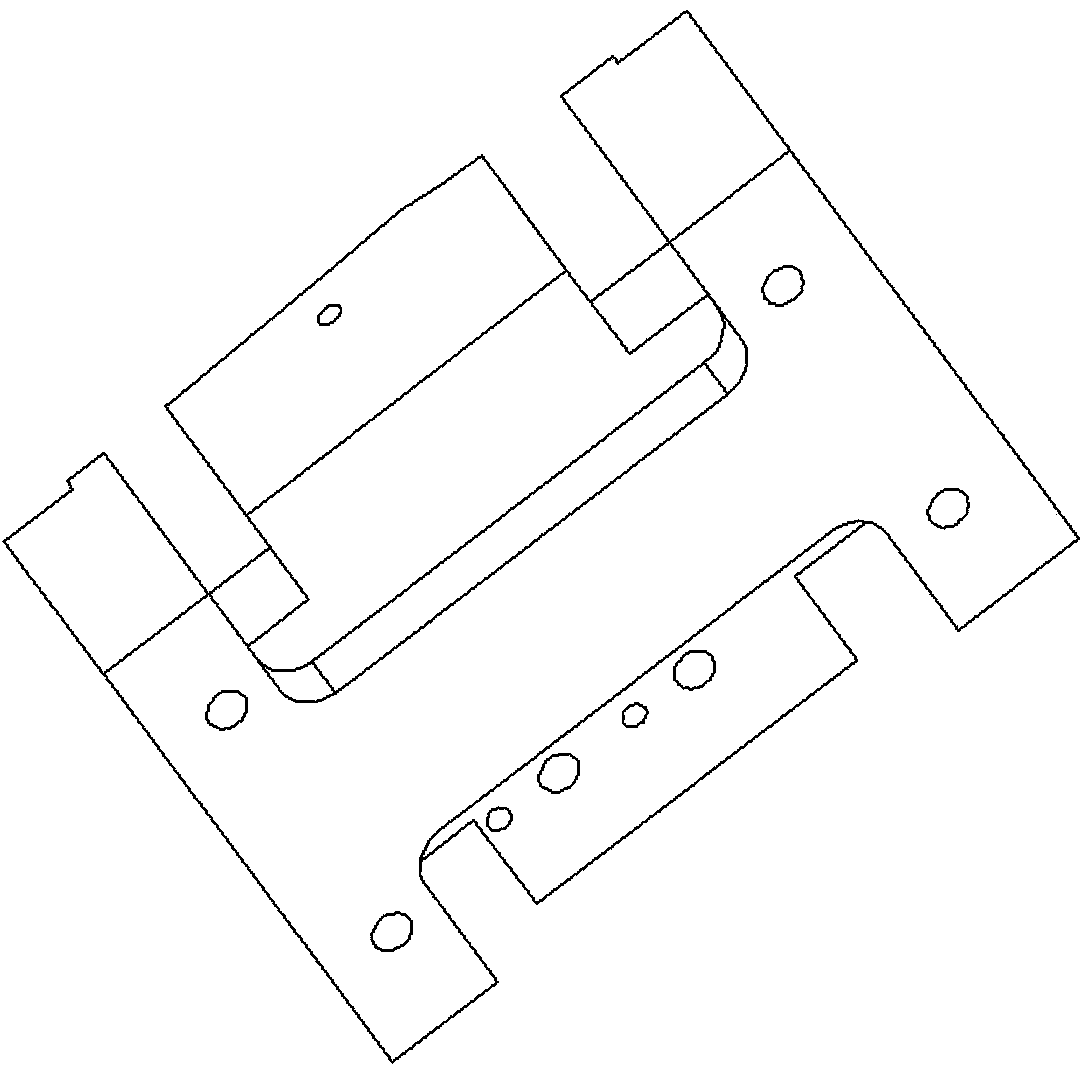
[0030] The directional solidification blade ceramic core forming device is constituted as follows: an upper template 1, an upper mold 2, a lower mold 3, an upper mold movable block 4, an upper mold pressing compacting block 5, a lower mold movable block 6, and a lower mold insert 7 , the front movable block 8 of the lower mold, the rear movable block 9 of the lower mold, the linkage plate 10, the front edge movable block 11, the wax injection plate 12, the stepped screw 13, the handle 14 and the positioning pin 15;

[0031] The lower mold 3 includes: the front side a of the lower mold and the bottom surface b of the lower mold, a core injection port is opened on the lef...

Embodiment 2

[0039] This embodiment is basically the same as Embodiment 1, the difference is:

[0040] The diameter of the core injection port opened at the left side A of the front side a of the lower mold is 8mm.

[0041] The shape of the openings at the four corners B of the front side a of the lower mold is square, and one side is rounded, and the sinking is 1.5 mm.

Embodiment 3

[0043] This embodiment is basically the same as Embodiment 1, the difference is:

[0044] The diameter of the core injection hole opened at the left side A of the front side a of the lower mold is 6-7mm.

[0045] The pry openings at the four corners B of the front side a of the lower mold are square in shape, and one side thereof is rounded, and sinks by 3.5 mm to 5 mm.


PUM

PropertyMeasurementUnit
Diameteraaaaaaaaaa

Abstract

The invention provides a device for molding a ceramic core of a directionally solidified blade. The device comprises an upper formwork (1), an upper mold (2), a lower mold (3), an upper mold loose piece (4), an upper mold pressing block (5), a lower mold loose piece (6), a lower mold insert (7), a lower mold front loose piece (8), a lower mold rear loose piece (9), a linking plate (10), a front edge loose piece (11), a wax injection plate (12), a stepped bolt (13), a handle (14) and a positioning pin (15), wherein the lower mold (3) comprises a front face a and a bottom face b; a core injection opening is formed in a part A on the left side of the front face a, and a positioning hole and a screw hole are respectively formed in the left end face of the front face a; the wax injection plate (12) is fixed on the lower mold (3) by virtue of the cylindrical pin (15) and the stepped bolt (13). The device has the advantages of high processing accuracy, compact assembly, small space, light weight and convenience in operation.

Description

technical field [0001] The invention relates to the structural design and application technical field of a directionally solidified blade ceramic core forming device. Background technique [0002] In order to continuously improve the thrust-to-weight ratio of aero-engines. The current solution is to increase the gas temperature in front of the aeroengine turbine and improve the cooling structure of the blades. However, the temperature bearing conditions of existing superalloy materials are close to the limit, so the design of turbine blades generally adopts a cavity structure to improve the cooling efficiency of the blades. The complex inner cavity of the hollow blade is formed by the ceramic core, so the manufacture of the ceramic core has also become a key technology in the casting of turbine blades. The manufacture of blades has developed from the initial equiaxed polycrystalline blades to directionally solidified columnar crystal blades and single crystal blades with c...

Claims


Application Information

Patent Timeline
IPC IPC(8): B22C9/10B22C7/00B22C9/24
CPCB22C9/10
Inventor 孙长波张泽海尚伟周君华邹建波
Owner SHENYANG LIMING AERO-ENGINE GROUP CORPORATION
Learn More