Method for dispensing a lubricant in a metered manner

A lubricant and reserve technology, used in lubricating parts, engine lubrication, dosing devices, etc., can solve problems such as dissatisfaction and inaccurate evaluation of lubricant dosage, and achieve the effect of improving distribution accuracy.

Active Publication Date: 2015-02-04
PERMA TEC
View PDF6 Cites 0 Cited by
  • Summary
  • Abstract
  • Description
  • Claims
  • Application Information

AI Technical Summary

Problems solved by technology

Due to these effects, the previously described evaluation of the delivered lubricant dose becomes increasingly imprecise and the use of preset values ​​for the dispensing duration leads to unsatisfactory results

Method used


Image

  • Method for dispensing a lubricant in a metered manner
  • Method for dispensing a lubricant in a metered manner

Examples


Embodiment Construction

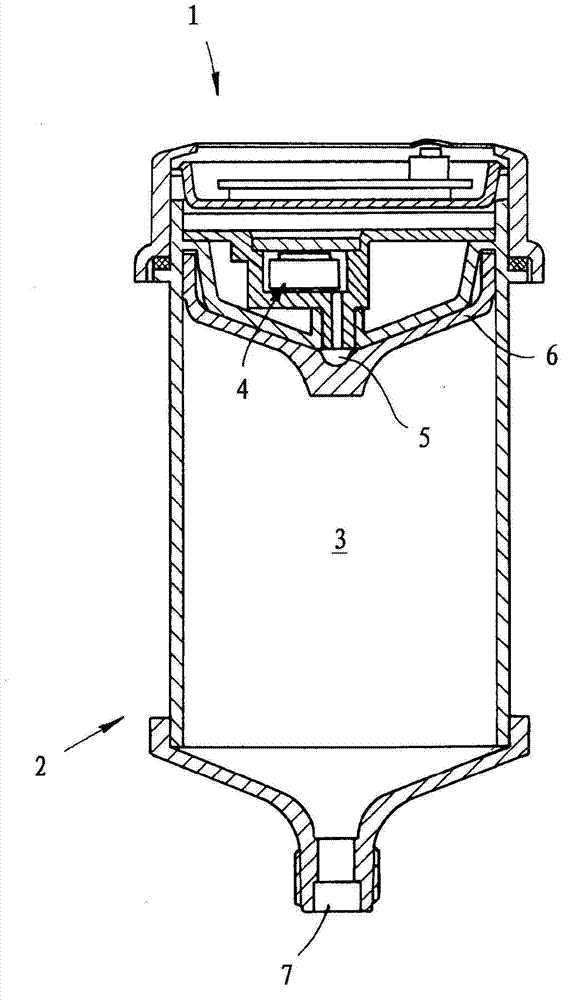
[0019] Control unit 1 and lubricant cartridge 2 belong to figure 1 The basic structure of the lubricant distributor shown in . Lubricant cartridge 2 is equipped with lubricant 3 in the inner chamber. Furthermore, the lubricant distributor includes at least one electrochemical gas generator unit 4 . The electronic control unit 1 regulates the current through the gas generator unit 4 and thereby controls the amount of gas generated therein. These gas quantities pass through the conduit into the chamber 5 behind the piston 6 which is arranged in the lubricant cartridge and delimits the lubricant reservoir by its side facing away from the chamber 5 . Due to the gas generation, an overpressure builds up in the chamber 5 , which is transmitted by the piston 6 to the lubricant. As a result, lubricant 3 is squeezed out of lubricant cartridge 2 and exits the lubricant cartridge through opening 7 .

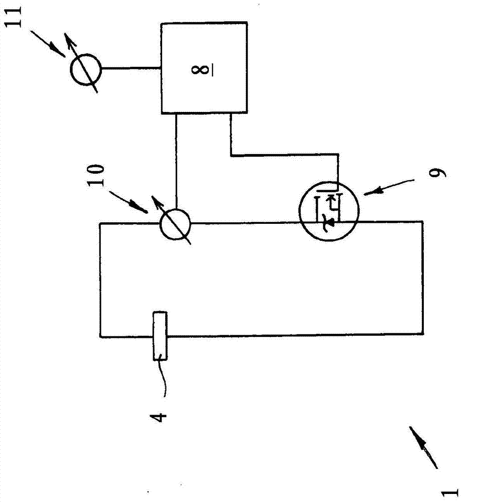
[0020] exist figure 2 A possible configuration of the circuit diagram of the elec...


PUM


Abstract

The invention relates to a method for dispensing a lubricant (3) in a metered manner by means of a lubricant dispenser, which comprises a lubricant cartridge (2) filled with lubricant (3), at least one electrochemical gas-generating cell (4), and on control electronics (1) for controlling the gas-generating cell (4). The control electronics (1) comprise a microcontroller (8) and a switch (9) for interrupting the current flowing through the gas-generating cell (4). At adjustable time intervals, the circuit through the gas-generating cell (4) is closed by the control electronics (1) and lubricant (3) is displaced from the cartridge (2) by the released gas. During the gas generation, the electric current flowing through the gas-generating cell (4) is measured and the charge that has flowed through the gas-generating cell (4) is added up. The circuit is interrupted when the added-up charge has exceeded a specified cumulative amount of charge.

Description

technical field [0001] The invention relates to a method for the metered delivery of lubricant by means of a lubricant distributor comprising a lubricant cartridge filled with lubricant, at least one electrochemical gas generator unit and means for controlling the Electronic control unit for the gas generator unit. The electronic control unit has a microcontroller and a switch for interrupting the current flow through the gas generator unit. By closing the electrical circuit through the gas generator unit, a gas is released in the gas generator unit which forces the lubricant out of the cartridge. Background technique [0002] In order to ensure economical and at the same time adequate lubrication, the lubricant output needs to be metered precisely. If the lubricant is dispensed at too short intervals or in too large a quantity, a very large amount of lubricant is required and the lubricant cartridge must be changed earlier than necessary. Conversely, poor lubrication can...

Claims


Application Information

Patent Timeline
Patent Type & Authority Applications(China)
IPC IPC(8): F16N11/00F16N11/10
CPCF16N2230/02F16N2250/08F16N11/10F16N2270/20F16N27/00F16N2250/50
Inventor R·莫泊J·莱纳特
Owner PERMA TEC
Why Eureka
Try Eureka