
Conductive spring for pins of power connector

A power connector and pin technology, which is applied in the field of conductive springs, can solve the problems of unfavorable power connector miniaturization, light weight production, large size of power connector, and limited flow capacity, etc., to achieve reliable contact and light weight Make and plug reliable results

Active Publication Date: 2017-01-18
CHINA AVIATION OPTICAL-ELECTRICAL TECH CO LTD
View PDF5 Cites 0 Cited by
  • Summary
  • Abstract
  • Description
  • Claims
  • Application Information

AI Technical Summary

Problems solved by technology

In order to realize the reliability of the insertion of pins and sockets, only the elastic part of the reed can be in contact with the pins, and the other sockets with elastic capabilities are similar, which results in the contact between the socket and the pins. The area is very limited, the contact resistance between the socket and the pin is large, and the flow capacity of the socket and the pin is limited. In order to improve the flow capacity of the pin and the socket, the diameter of the pin can only be increased. Increasing the contact area between pins and jacks will lead to a larger size of the corresponding power connector, which is not conducive to the miniaturization and lightweight production of the power connector

Method used


Image

  • Conductive spring for pins of power connector
  • Conductive spring for pins of power connector
  • Conductive spring for pins of power connector

Examples


Embodiment Construction

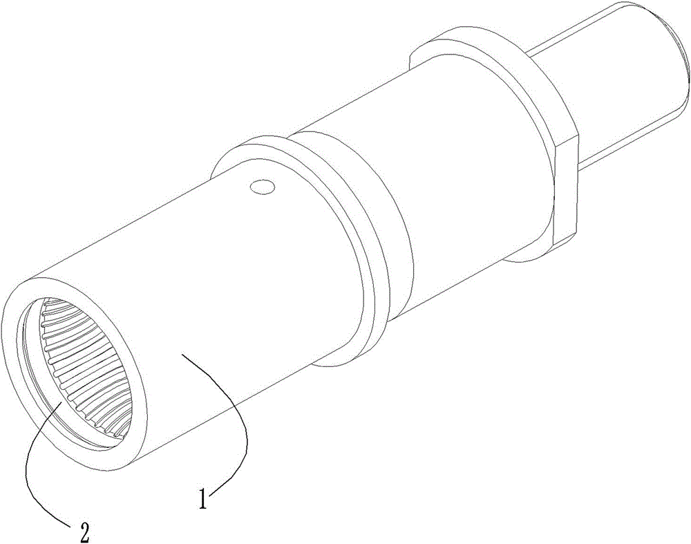
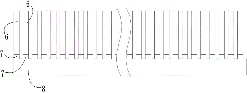
[0021] Examples of conductive springs are Figure 3~8 Shown: The structure of the conductive spring is as follows Figure 3~4 As shown, it includes a strip-shaped flexible base 8 extending along the front-to-rear direction for being wound and fixed on the outer periphery of the corresponding pin during use. The strip-shaped flexible base 8 is a sheet-shaped structure whose thickness extends along the front-to-back direction. The conductive spring also includes a plurality of Elastic contact fingers 6, the lower ends of each elastic contact finger 6 protrude backward respectively and are used for positioning positioning protrusions 7 and strip-shaped flexible substrates 8 inserted in the spiral positioning grooves on the outer peripheral surface of the pins. connection, the upper end of each elastic contact finger 6 is an elastic overhang end elastically overhanging the upper side of the strip-shaped flexible substrate 8 with elastic deformation in the front-rear direction, eac...


PUM


Abstract

The invention relates to a conductive spring for an insertion pin of a power connector. The conductive spring comprises a bar-type flexible base body which extends along the left and right direction and for being twined and fixed to the outer circumference of the corresponding insertion pin during using. The conductive spring also comprises a plurality of elastic touch fingers. The lower end of each elastic touch finger is directly or indirectly connected with the bar-type flexible base body; the upper end of each elastic touch finger is an elastic overhanging end which is elastically overhanging to the upper side of the bar-type flexible base body and has elastic deformation quantity along the front and rear direction; and the elastic overhanging end of each elastic touch finger is provided with a contact portion for being in elastic contact cooperation with hole wall of a corresponding insertion hole. The invention provides the conductive spring which can improve the contact area of the insertion pin and the insertion hole and is used for the insertion pin of the power connector.

Description

technical field [0001] The invention relates to a conductive spring for pins of a power connector. Background technique [0002] The contacts used in power connectors that transmit large currents are divided into pins and sockets, and the pins are used to be inserted into the sockets to realize signal transmission. The reliability of the socket connection, the socket is generally an elastic member with elastic capacity, such as an opening hole, a wire spring hole, a crown belt hole, etc. Now take the coronet hole as an example to illustrate the problems existing in the socket in the prior art. The structure of the cap hole is as follows: Figure 1~2 As shown, it includes a jack body 1 and a crown spring 2 arranged in the inner hole of the jack body. The crown spring includes a front ring 3, a rear ring 5 and a plurality of reeds 4 connected between the front and rear rings. The middle part of the reed protrudes toward the center line of the crown spring, so each reed has th...

Claims


Application Information

Patent Timeline
Patent Type & Authority Patents(China)
IPC IPC(8): H01R13/17H01R13/40
CPCH01R13/17
Inventor 李强
Owner CHINA AVIATION OPTICAL-ELECTRICAL TECH CO LTD
Learn More