Critical clearing time method for power system disturbance based on frequency synchronization theory of second-order inhomogeneous Kuramoto model
A power system and cut-off time technology, which is applied in the fields of electrical digital data processing, special data processing applications, instruments, etc., can solve problems such as the study of the attractive domain of the system equilibrium point, the inability to correspond to the power system model, and the inability to apply transient stability analysis. , to achieve the effect of accurate and reliable calculation results and fast calculation speed
- Summary
- Abstract
- Description
- Claims
- Application Information
AI Technical Summary
Problems solved by technology
Method used
Image
Examples
specific Embodiment approach 1
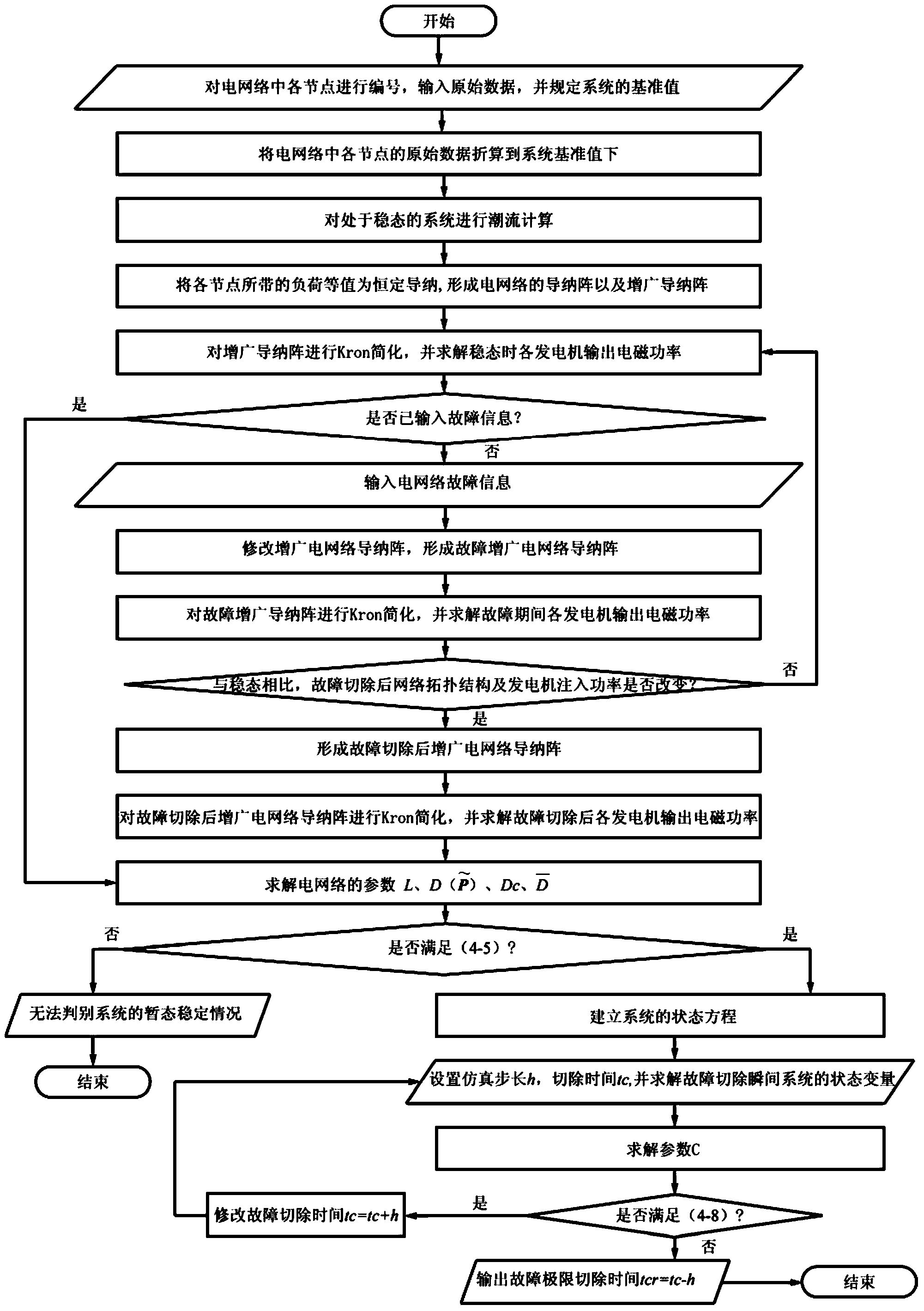
[0020] Specific embodiment one: the power system disturbance limit cut-off time method based on the second-order non-uniform Kuramoto model frequency synchronization theory of the present embodiment, it is realized according to the following steps:
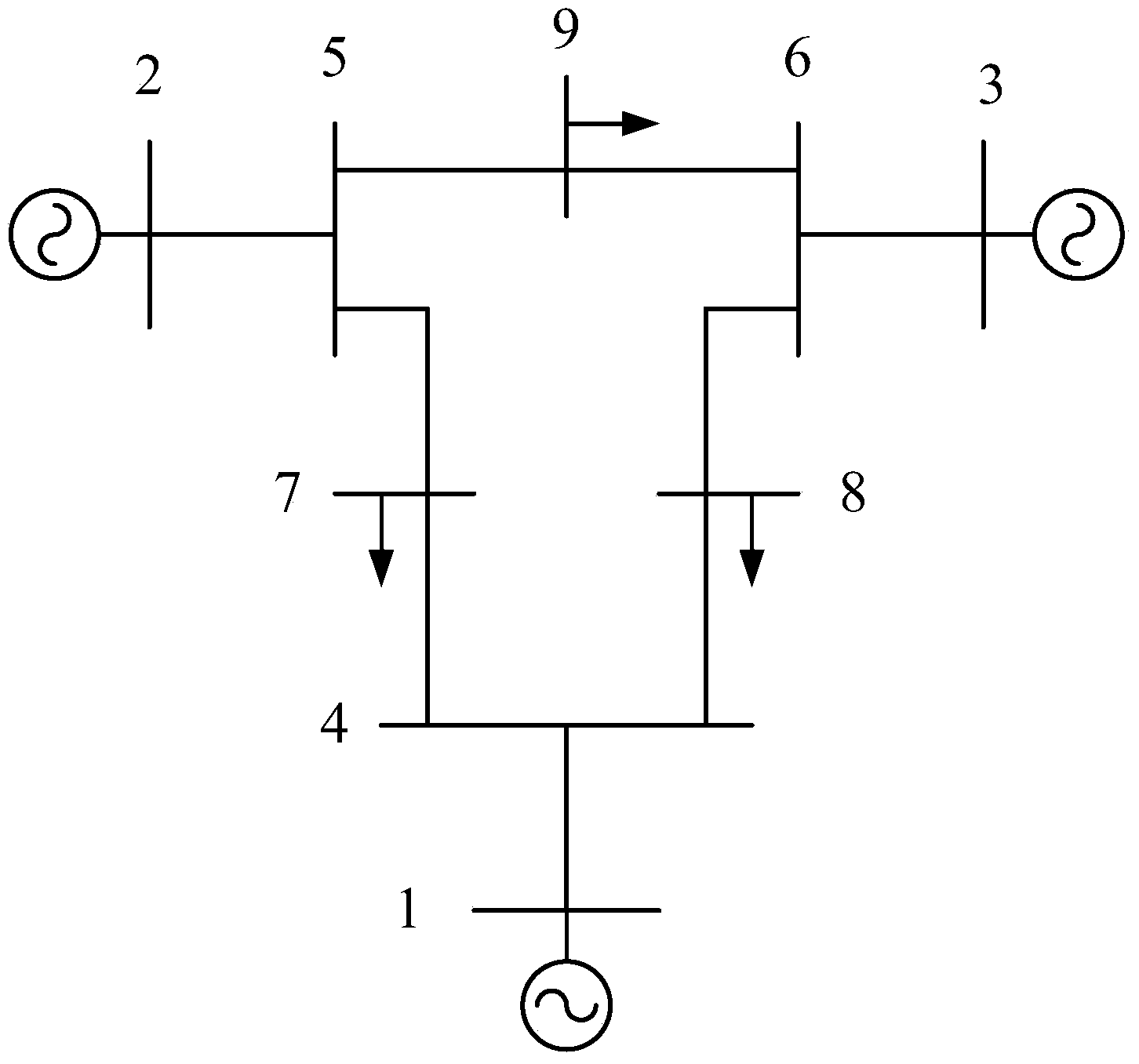
[0021] Step 1: Establish a second-order non-uniform Kuramoto model corresponding to the power system model, and calculate the power output and transmission power of the power system, simplify the grid network to a fully connected grid network that only includes internal nodes of the generator, and form a second-order non-uniform The correspondence between the natural frequency term in the uniform Kuramoto model and the coupling coefficient of the network and the power output and transmission power in the power system;
[0022] Step 2: If a node in the power system is disturbed, modify the parameters of the second-order non-uniform Kuramoto model according to the structure of the grid network after the disturbance is removed;
[00...
specific Embodiment approach 2
[0029] Specific implementation mode two: the difference between this implementation mode and specific implementation mode one is that the step one is specifically:
[0030] Step 11: Establish a second-order non-uniform Kuramoto model corresponding to the power system model, and convert the original data of the analysis system to a unified benchmark value:
[0031] First, for a power system with n generators, in the case of disturbance, the equation of each generator can be written as
[0032] M i d 2 δ i dt 2 + D i d δ i dt = P mi - P ei , ...
specific Embodiment approach 3
[0056] Specific implementation mode three: the difference between this implementation mode and specific implementation mode one or two is that: in the step two, it is specifically:
[0057] Step 21: First, use the Kron reduction method to shrink the grid network to a fully connected network that only includes nodes in the generator. If a node in the system is disturbed, set the initial disturbance removal time t c = 0.001s;
[0058] Step 22: According to the structure of the power grid network after the disturbance removal, modify the admittance array of the augmented network to form the admittance array of the augmented network after the disturbance removal, and perform an equivalent value on the admittance array of the augmented network after the disturbance removal ;
[0059] Step two and three: For a power system with n generators, δ(t)=(δ 1 (t),...,δ n (t)), ω(t)=(ω 1 (t),...,ω n (t)) respectively represent the set of rotor angle and angular velocity of each generato...
PUM
 Abstract
Description
Claims
Application Information
 - R&D
- Intellectual Property
- Life Sciences
- Materials
- Tech Scout
- Unparalleled Data Quality
- Higher Quality Content
- 60% Fewer Hallucinations
Browse by: Latest US Patents, China's latest patents, Technical Efficacy Thesaurus, Application Domain, Technology Topic, Popular Technical Reports.
© 2025 PatSnap. All rights reserved.Legal|Privacy policy|Modern Slavery Act Transparency Statement|Sitemap|About US| Contact US: help@patsnap.com


