
System and method for recycling and reusing vibration energy of road roller

A vibration energy recovery and road roller technology, which is applied in the field of road rollers, can solve the problems of pressure shock, low work efficiency, waste of rotational kinetic energy, etc., and achieve the effects of prolonging the life of components, reducing pressure shock and improving reliability

Active Publication Date: 2015-02-04
LINDE HYDRAULICS CHINA CO LTD
View PDF7 Cites 7 Cited by
  • Summary
  • Abstract
  • Description
  • Claims
  • Application Information

AI Technical Summary

Problems solved by technology

[0003] Due to the large moment of inertia of the vibration system, the vibration motor needs to consume a lot of power to push the vibration block when starting the vibration. In order to prevent the engine from stalling, it is necessary to use a larger displacement engine. After normal operation, the power consumption of the vibration system is only It accounts for about 40% of the peak power in the starting process, making the engine work in the low load area, and the work efficiency is low
During the vibration stop period, due to the existence of the rotating inertial force of the high-speed vibrating block, the vibrating block drives the vibrating motor to operate under pump conditions, causing a huge pressure shock. In addition to negatively affecting the reliability of the system, these rotational kinetic energy also wasted

Method used


Image

  • System and method for recycling and reusing vibration energy of road roller
  • System and method for recycling and reusing vibration energy of road roller

Examples


Embodiment Construction

[0037] In order to make the objectives, technical solutions, and advantages of the embodiments of the present invention clearer, the technical solutions in the embodiments of the present invention will be described clearly and completely in conjunction with the accompanying drawings in the embodiments of the present invention. Obviously, the described embodiments It is a part of the embodiments of the present invention, not all the embodiments. Based on the embodiments of the present invention, all other embodiments obtained by those of ordinary skill in the art without creative work shall fall within the protection scope of the present invention.

[0038] The vibration energy recovery and reuse system and method provided by the embodiments of the present invention mainly recover the rotational kinetic energy of the vibration system when the vibration is stopped, and can apply the recovered rotational kinetic energy to the start-up process, so as to save energy and increase the li...


PUM


Abstract

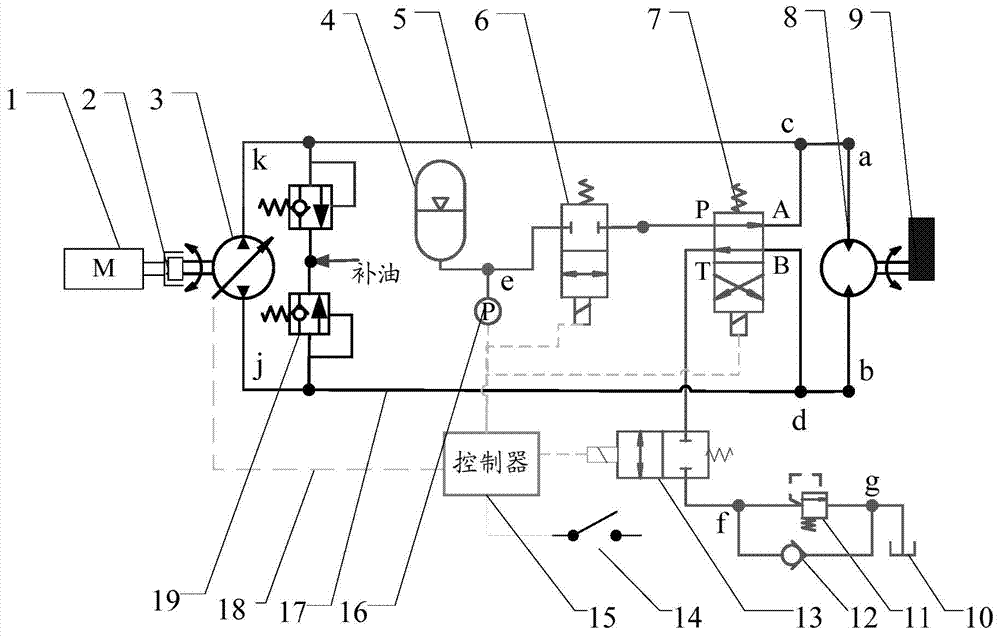
The invention discloses a system and a method for recycling and reusing the vibration energy of a road roller. In the vibration stop process, a first path formed by a first two-position two-way on-off valve, a two-position four-way reversing valve and a second two-position two-way on-off valve is controlled, and the rotational kinetic energy of a vibrating motor is converted into pressure energy and is accumulated in a high pressure energy accumulator through the first path; a low pressure oil tank, a one-way valve, the second two-position two-way on-off valve, the T end to the A end of the two-position four-way reversing valve, the vibrating motor, the B end to the P end of the two-position four-way reversing valve, the first two-position two-way on-off valve and the high pressure energy accumulator are arranged in the first path in sequence; or, the low-pressure oil tank, the one-way valve, the second two-position two-way on-off valve, the T end to the B end of the two-position four-way reversing valve, the vibrating motor, the A end to the P end of the two-position four-way reversing valve, the first two-position two-way on-off valve and the high pressure energy accumulator are arranged in the first path in sequence; moreover, according to the system and the method, the pressure energy accumulated in the high pressure energy accumulator can be used for the vibration stop process further.

Description

Technical field [0001] The invention relates to the technical field of road rollers, and in particular to a system and method for recycling vibration energy of a road roller. Background technique [0002] In order to improve the effect of road compaction, most modern road rollers are equipped with a vibration system. The vibration system is a system that generates vibration in the rollers of the roller to enhance the compaction rate of the roller. The vibration system works when the roller is moving forward or backward. During the working process, a certain frequency and amplitude vibration will be generated on the roller of the roller. Due to the large moment of inertia of the vibration system, in order to keep the vehicle speed as stable as possible during the start of the roller, the start of the roller is required to follow the process of starting walking -> starting vibration -> working -> stopping vibration -> stopping walking. When the roller changes from forw...

Claims


Application Information

Patent Timeline
Patent Type & Authority Applications(China)
IPC IPC(8): F15B1/02E01C19/23
CPCE01C19/23F15B1/02F15B1/021
Inventor 刘林倪林
Owner LINDE HYDRAULICS CHINA CO LTD
Learn More