
High-power microwave phased-array antenna with reconfigurable leftward and rightward rotation circular polarization

A phased array antenna, circularly polarized technology, applied in the direction of the antenna, antenna array, antenna grounding switch structure connection, etc., can solve the problems that cannot be changed, the reconfigurable technology cannot meet the requirements of high-power microwave power capacity, etc. The effect of power capacity

Active Publication Date: 2015-01-28
INST OF APPLIED ELECTRONICS CHINA ACAD OF ENG PHYSICS
View PDF5 Cites 18 Cited by
  • Summary
  • Abstract
  • Description
  • Claims
  • Application Information

AI Technical Summary

Problems solved by technology

[0003]In order to enable high-power microwaves to have fast beam scanning capabilities, Southwest Jiaotong University proposed a phased array technology based on short helical antennas, but once the circular polarization direction of the antenna Once designed, it cannot be changed
The current polarization reconfigurable antennas are all based on controllable diode technology, which controls the conduction and disconnection of the diode through the DC bias voltage to change the antenna current distribution, thereby realizing polarization, pattern or frequency reconfiguration, but at high In the field of power microwaves, the reconfigurable technology based on controllable diodes is far from meeting the power capacity requirements of high-power microwaves, so there is an urgent need for a high-power phased array antenna with beam two-dimensional scanning and polarization reconfigurable

Method used


Image

  • High-power microwave phased-array antenna with reconfigurable leftward and rightward rotation circular polarization
  • High-power microwave phased-array antenna with reconfigurable leftward and rightward rotation circular polarization
  • High-power microwave phased-array antenna with reconfigurable leftward and rightward rotation circular polarization

Examples


Embodiment

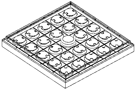
[0033] Design a working frequency according to the above-mentioned invention scheme f 0 =1.575GHz (L-band) left-hand circularly polarized reconfigurable high-power microwave phased array antenna, its structure is as follows figure 1 , figure 2 As shown, the phased array consists of 24 radiation elements forming a 5×5 array, the array element in the center is vacant, the array element spacing is 110mm×110mm, and the array size is 580mm×580mm.

[0034] The high-power microwave with a power of 240MW is input from the coaxial feed-in port on the back. The inner and outer diameters of the coaxial port are 80mm and 40mm (impedance 40Ω). After the microwave is converted to radial line propagation, the equal power is coupled to 24 radiation units. Each unit has a power of 10MW.

[0035] Radiation unit design structure such as image 3 Shown:

[0036] The diameter of the circular patch is 72mm, the thickness is 2mm, and the symmetrical rectangular notch is 15mm wide and 18mm deep...


PUM


Abstract

The invention belongs to the technical field of high-power microwave transmitting antennas, and provides a high-power microwave phased-array antenna with reconfigurable leftward and rightward rotation circular polarization, wherein the high-power microwave transmitting antenna also has two-dimensional phase scanning and polarization reconfiguration functions. According to the high-power microwave phased-array antenna, reconfiguration leftward and rightward rotation circular polarization patch antenna units form an array, so angular phase rotation of array elements and polarization configuration can be achieved by means of one motor, and the array has the beam two-dimensional phase scanning function and the on-line real-time polarization reconfiguration function simultaneously. The high-power microwave phased-array antenna can be widely used for the fields of high-power microwave transmitting, high-power microwave transmitting, electronic countermeasure, phase control radar and the like.

Description

technical field [0001] The invention relates to the field of high-power microwave transmitting antennas, in particular to a reconfigurable phased array antenna with left and right circular polarization. Background technique [0002] High Power Microwave technology (High Power Microwave) is a new subject field derived from nuclear technology. It is a comprehensive subject combining pulse power technology, relativistic electric vacuum devices, antenna technology and other disciplines. Among them, the role of the high-power microwave antenna is to directional launch the high-power microwave generated by the relativistic electric vacuum device into space, which plays a key role in the high-power microwave system. [0003] In order to enable high-power microwaves to have fast beam scanning capabilities, Southwest Jiaotong University proposed a phased array technology based on short helical antennas, but once the circular polarization direction of the antenna is designed, it canno...

Claims


Application Information

Patent Timeline
IPC IPC(8): H01Q15/24H01Q21/00H01Q1/50H01Q3/32
Inventor 许州徐刚马弘舸廖勇陈世韬谢平施美友
Owner INST OF APPLIED ELECTRONICS CHINA ACAD OF ENG PHYSICS
Learn More