
General-purpose optical fiber connector

A fiber optic connector, a general-purpose technology, applied in the field of general-purpose fiber optic connectors, can solve problems such as damage to the quality of connection points, waste of connectors, waste of materials, etc., to improve production efficiency, enhance tensile performance, and improve resources. The effect of using

Active Publication Date: 2015-01-28
INNO INSTR (CHINA) INC +1
View PDF5 Cites 9 Cited by
  • Summary
  • Abstract
  • Description
  • Claims
  • Application Information

AI Technical Summary

Problems solved by technology

When clamping a square optical fiber (for example, a leather cable), because the optical fiber buckle often cannot be snugly clamped to the two opposite sides of the square optical fiber, this will cause the spliced ​​optical fiber to rotate as the nut is tightened. Tight operation and rotation, resulting in damage to the connection quality of the connection point, or even the failure of the connector;
[0005] 2. Due to the different sizes and thicknesses of the spliced ​​optical fibers, the existing optical fiber connectors need to produce various types of products to be suitable for certain specifications of optical fibers; or, although they can be applied to various optical fibers, the tensile performance is far from Does not meet the desired effect
[0006] 3. Since there are many types of optical fiber connectors, each type of optical fiber connector has its own corresponding protective cover according to the structure and size of the thermal fusion head, so the protective cover is not compatible. When a type of optical fiber connector is protected After the cover is damaged, you can only replace the same type of protective cover, or discard it, so you can't save materials, and there is a problem of wasting materials

Method used


Image

  • General-purpose optical fiber connector
  • General-purpose optical fiber connector
  • General-purpose optical fiber connector

Examples


Embodiment Construction

[0032] The general optical fiber connector provided by the embodiment of the present invention will be further described in detail below with reference to the accompanying drawings. However, the embodiments of the present invention and the components shown in the drawings are only preferred embodiments of the present invention, and cannot replace the technical idea of ​​the present invention. The terms and words used in the description and the claims are only for explaining the technical solution of the present invention in the best way, and should not be construed as limiting the technical idea of ​​the present invention.

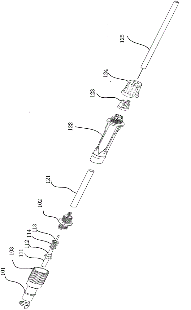
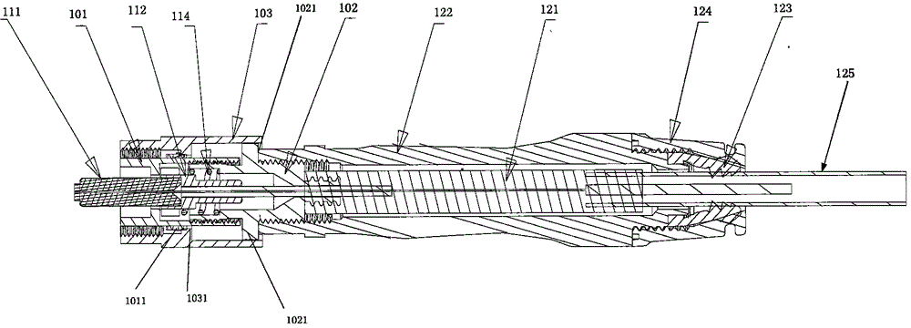
[0033] The core idea of ​​the present invention is to provide a general-purpose optical fiber connector, which includes a heat-melt connector assembly, a heat-shrinkable sleeve, and a heat-shrinkable sleeve protective shell, wherein the heat-melt connector assembly is further It includes the main body of the hot-melt head, the ceramic ferrule, the ceramic ...


PUM


Abstract

The invention relates to a general-purpose optical fiber connector. The general-purpose optical fiber connector comprises a hot melting connector assembly, a heat-shrinkable sleeve and a heat-shrinkable sleeve protective shell. The hot melting connector assembly comprises a hot melting head body, a ceramic pin, a ceramic pin holder base and an embedded optical fiber, wherein the ceramic pin, the ceramic pin holder base and the embedded optical fiber are arranged in the hot melting head body in a penetration mode. The tail portion of the heat-shrinkable sleeve protective shell is connected to an optical fiber locking device for locking the optical fiber and the locking device is arranged in separation from the heat-shrinkable sleeve protective shell. The general-purpose optical fiber connector is compatible with optical fibers in different sizes, the tensile property of the optical fiber connector is enhanced, and the heat-shrinkable sleeve protective shell can use the same mold for mass production rather than separate production for each type, so that the production efficiency is improved.

Description

technical field [0001] The invention relates to the technical field of optical fiber connection, in particular to a general-purpose optical fiber connector for thermal fusion splicing. Background technique [0002] The fiber optic direct to the home (Fiber To The Home, FTTH) technology connects the optical cable to the general household, and can provide various information including broadcasting and communication. This technology can be applied to apartments, houses, etc. The FTTH system is connected into the home and its ends are provided in the form of fiber optic connectors. At this time, FTTH workers consider the connection between optical cables, set the length of the optical cable to several meters longer than the measured length, and then introduce it into the home. And cut the required length of optical fiber cable in the home at the construction site, assemble the optical fiber connector at the end, connect it to the optical adapter and install it in the home. [...

Claims


Application Information

Patent Timeline
IPC IPC(8): G02B6/255
CPCG02B6/2558G02B6/3889G02B6/3861G02B6/3846G02B6/4476G02B6/3871
Inventor 张玉中金勋
Owner INNO INSTR (CHINA) INC
Learn More