
Absolute capacitor and differential capacitor measuring circuit

A technology of differential capacitance and absolute capacitance, applied in the direction of measuring electrical variables, measuring resistance/reactance/impedance, measuring devices, etc., can solve the problems of complex measurement circuit, large output nonlinearity, poor dynamic characteristics, etc., and achieve simple circuit structure , Small footprint and low cost

Inactive Publication Date: 2015-01-28
JILIN UNIV
View PDF11 Cites 2 Cited by
  • Summary
  • Abstract
  • Description
  • Claims
  • Application Information

AI Technical Summary

Problems solved by technology

The main problems are: large output nonlinearity; poor dynamic characteristics
This method has high measurement accuracy, but it needs to provide sine wave or square wave and positive and negative power supply, so the measurement circuit is complicated and the cost is high

Method used


Image

  • Absolute capacitor and differential capacitor measuring circuit
  • Absolute capacitor and differential capacitor measuring circuit
  • Absolute capacitor and differential capacitor measuring circuit

Examples


Embodiment Construction

[0034] The present invention will be further described in detail below in conjunction with the embodiments and the accompanying drawings, but the implementation of the present invention is not limited thereto.

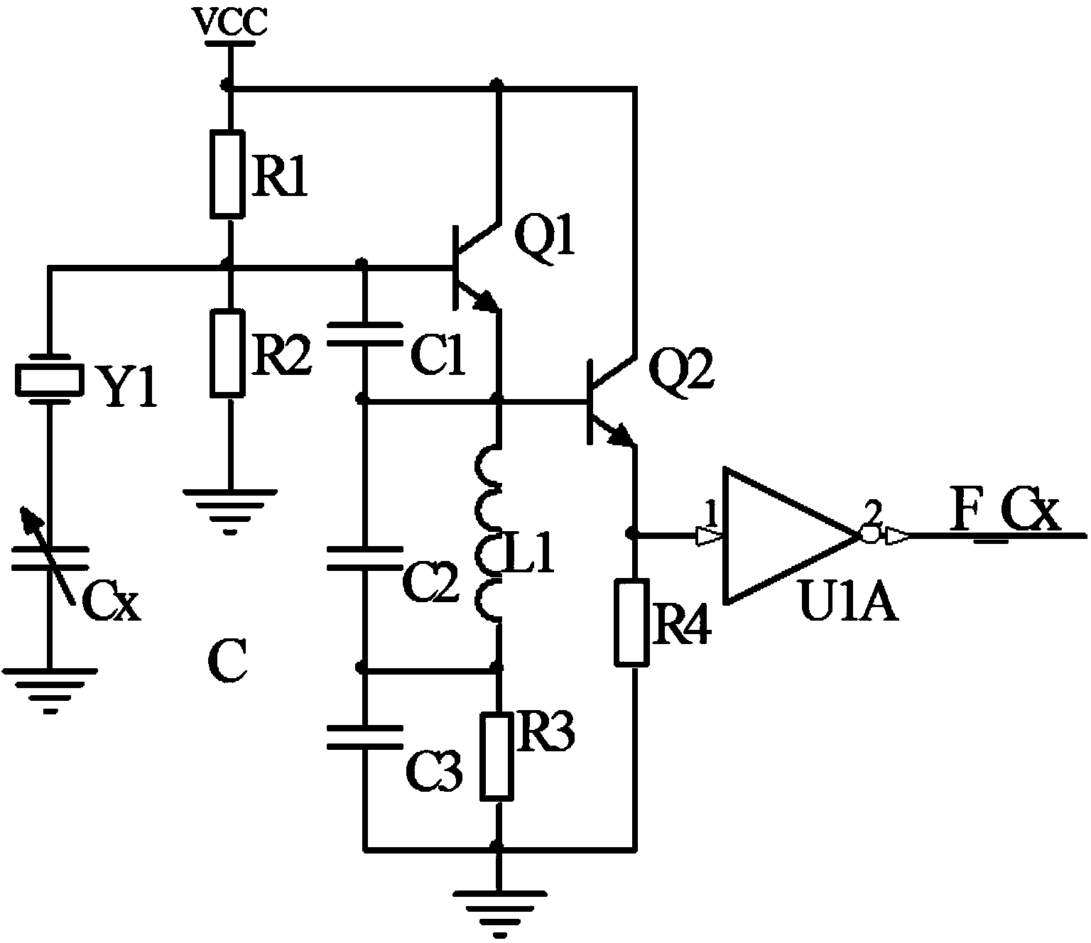
[0035] 1. The circuit diagram of a crystal oscillating circuit for measuring absolute capacitance is as follows: figure 1 As shown, the specific implementation steps are as follows:

[0036] (1) figure 1 The invention is a crystal oscillator circuit for measuring absolute capacitance in an absolute capacitance and differential capacitance measuring circuit of the present invention. Such as figure 1The circuit shown includes two NPN transistors Q1 and Q2, four resistors R1, R2, R3 and R4, three known capacitors C1, C2 and C3, an inductor L1, a crystal oscillator Y1, and an inverting Device U1A and the capacitance Cx to be measured.

[0037] (2) if figure 1 The first terminal of the capacitor Cx to be tested is grounded, and the second terminal is connected to the f...


PUM


Abstract

The invention discloses an absolute capacitor and differential capacitor measuring circuit and method. The absolute capacitor and differential capacitor measuring circuit comprises a crystal oscillation circuit for measuring an absolute capacitor and a circuit for measuring a differential capacitor, and the absolute capacitor and differential capacitor measuring method comprises a method for measuring the absolute capacitor and a method for measuring the differential capacitor. According to the absolute capacitor and differential capacitor measuring circuit, the principle of the crystal oscillation circuit is utilized, all elements are common electronic elements, the structure is simple, the floor area of the circuit is small, and the elements are convenient to purchase, low in power consumption and extremely low in cost; a single power supply is adopted for supplying electricity to the circuit, voltage of a VCC of the power supply ranges from 2V to 6V, a TTL and a CMOS level are completely compatible, and the circuit has a wider application range; the resolution of the circuit mainly depends on frequency measurement precision, an existing frequency measurement technology is mature, and high-precision capacitance measurement can be achieved; according to the circuit for measuring the differential capacitor, a frequency difference is extracted only by using a data flip-flop; the circuit for measuring the differential capacitor is simple and can be used for measuring not only the differential capacitor but also the absolute capacitor.

Description

technical field [0001] The invention relates to a capacitance measuring circuit and method, in particular to a capacitance measuring circuit and method using a crystal oscillator circuit to measure absolute capacitance and differential capacitance, and belongs to the field of electrical and electronic measurement methods and devices. Background technique [0002] At present, capacitance measurement and processing circuits can be roughly divided into: frequency modulation circuit, bridge method, DC charging and discharging circuit, synchronous demodulator method, etc. [0003] (1) The frequency modulation method is also called the oscillation circuit method, which is based on the idea of ​​capacitance / frequency conversion to detect the measured capacitance. This method is to place the capacitive sensor in the LC or RC resonant circuit to form an oscillating circuit. When the measured capacitance changes, the oscillating frequency of the oscillating circuit will change accordi...

Claims


Application Information

Patent Timeline
IPC IPC(8): G01R27/26
Inventor 梁亮石屹然周秀文石要武高伟李新波马彦方盛洲付云博
Owner JILIN UNIV
Learn More