
Folding grip shield

A shield and grip technology, applied to defenses and other directions, can solve the problems of wrist injury, adjustment, and fixed handle occupying a large space, achieving good economic and social benefits, saving storage space, and saving transportation costs.

Active Publication Date: 2015-01-28
JIANGSU WUWEI POLICE EQUIP MFG
View PDF10 Cites 19 Cited by
  • Summary
  • Abstract
  • Description
  • Claims
  • Application Information

AI Technical Summary

Problems solved by technology

If the above patents are adopted, although the problem of taking up a large space for the fixed handle is solved and the space occupied by the bulletproof and riot shield is reduced, the following defects still exist: the handle can rotate in the shaft hole when in use, and the shield is even subjected to a small impact. , since the handle cannot be fixed and the direction of rotation is unpredictable, with the sudden change of the force point, it is easy to cause damage to the user's wrist
If this patent is adopted, the handle body is pulled up to make the retaining nails snap into the baffle, and the baffle is blocked by the handle seat B, which prevents the handle body from being pushed to the left, but there are still the following defects: 1), the position of the baffle is blocked Limited by the torsion spring, the angle of the handle body cannot be adjusted according to the user's habits; 2) If baffles are installed on both sides of the handle seat B, the handle body cannot rotate; 3) The push of the handle body to the left is blocked, Can still be pushed to the right, still hurts the user's wrist

Method used


Image

  • Folding grip shield
  • Folding grip shield
  • Folding grip shield

Examples


Embodiment 1

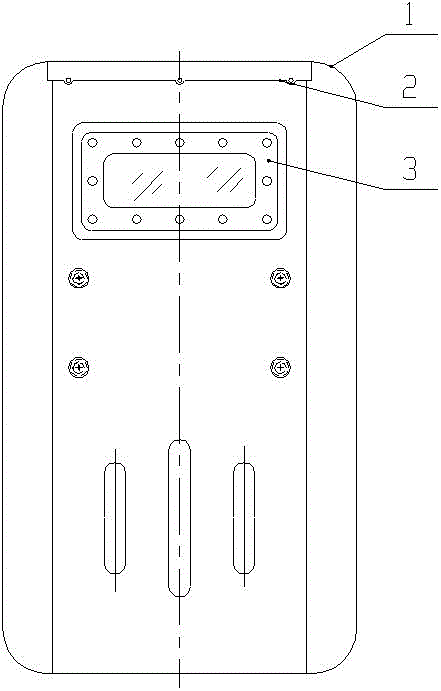
[0017] Embodiment 1. The shield 1 is made of transparent PC, and the observation window 3 is not provided;

Embodiment 2

[0018] Embodiment 2: The shield 1 is made of aluminum alloy or bulletproof fiber, the observation window 3 is provided with a steel convex fixed frame on the front of the shield 1, and the observation window 3 is provided with an engineering plastic fixed frame on the back of the shield 1, and is arranged between the two fixed frames. There is one layer of 2mm PC boards and one layer of 3mm PC boards. There is a PVC buffer pad between the PC boards, and a PVC buffer pad between the engineering plastic fixing frame and the shield 1. The two fixing frames are connected by 12 sets of bolts and nuts.

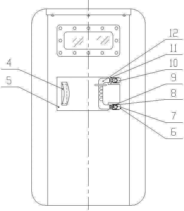
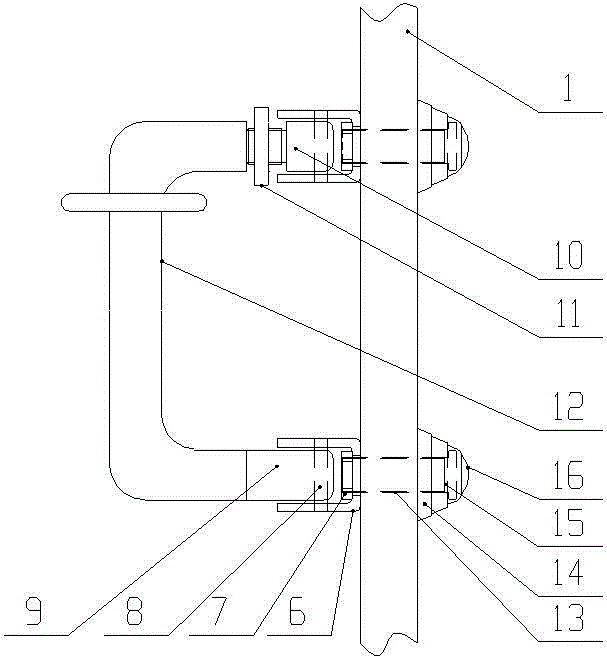
[0019] During specific implementation, the fixing bolt 13 passes through the bolt fixing sleeve 15, the bolt shock pad 14, the shield 1, and the fixing bracket 6 successively from the front of the shield 1, and is fixed with the lock nut 7; the fixing belt 4 passes through the buffer layer 5; The bolt cover 16 is pressed onto the bolt fixing sleeve 15 to prevent the bolts from being ...


PUM


Abstract

The invention discloses a folding grip shield. The middle of the back of the shield is provided with a buffer layer; the buffer layer is adhered to the shield by adhesive; the upper left side of the buffer layer is provided with a longitudinal fixing band; the right side of the buffer layer is provided with two longitudinal fixing brackets; a grip is fixedly connected with the fixing brackets by a rotary long joint, a rotary short joint and a rotary pin; the rotary short joint can rotate in the C-shaped groove of the corresponding fixing bracket around the rotary pin; a junction of the top of the grip and the rotary short joint is provided with a knurling non-return sleeve; the knurling non-return sleeve can rotate to the notch of the C-shaped groove of the corresponding fixing bracket and compress to fix the grip; the bottom of the grip is in threaded connection with the rotary long joint; the rotary long joint can rotate in the C-shaped groove of the corresponding fixing bracket around the rotary pin. The folding grip shield has the advantages of reasonable structure, flexibility in use, storage space saving and transportation cost saving, the wrist position of a user can be protected, and the angle of the grip can be regulated according to the habits of the user.

Description

technical field [0001] The invention belongs to the field of police equipment, in particular to a shield with a folding handle. Background technique [0002] At present, my country's society is stable, but factors of instability still exist. The possibility of hyping up hot and sensitive issues and hostile forces interfering to trigger large-scale mass incidents cannot be ruled out. At present, shields, as the main equipment for anti-riot and riot control, are widely used in the army and public security system, and play a role in protecting the safety of law enforcement officers when dealing with emergencies and daily law enforcement. Riot shields have the function of blocking bricks, stones, sticks, glass bottles or daggers and other objects from hitting and sprinting. Anti-riot shields are all provided with handles for users to grasp, but since the handles protrude from the shield body, the space required for transportation and storage of the anti-riot shields is relative...

Claims


Application Information

Patent Timeline
Patent Type & Authority Applications(China)
IPC IPC(8): F41H5/08
Inventor 倪峻峰
Owner JIANGSU WUWEI POLICE EQUIP MFG
Learn More