Control system for movable formwork template

A technology of moving formwork and control system, applied in the direction of fluid pressure actuating device, servo motor, servo motor assembly, etc. The effect of avoiding deformation or even damage

Inactive Publication Date: 2015-01-28
SHANDONG HENGKUN MACHINERY
View PDF8 Cites 3 Cited by
  • Summary
  • Abstract
  • Description
  • Claims
  • Application Information

AI Technical Summary

Problems solved by technology

In the past, the hydraulic system was only regulated by a synchronous valve or a throttle valve, and the synchronization performance was poor. However, due to the short stroke of the mold opening cylinder, the synchronization error can be eliminated in each stroke of the cylinder, so the previous hydraulic system can still barely meet the use requirements.
If the template hydraulic cylinder has a large stroke, there will be large errors and differences between the hydraulic cylinders of the previous system, which will cause the template to be deformed or even damaged, which cannot meet the use requirements
In the past, the hydraulic system could realize single-action and linkage operation through electrical control, but the speed difference between the linkage and single-action cylinders was large, often reaching several times the difference, resulting in very poor handling performance and usability
The mobile formwork is a large-scale equipment, and the formwork cylinders are distributed far away. In the past, the operating devices of the hydraulic system were concentrated on the control cabinet, and the operator could not observe the movement of the cylinder. extremely inefficient

Method used


Image

  • Control system for movable formwork template
  • Control system for movable formwork template
  • Control system for movable formwork template

Examples


Embodiment Construction

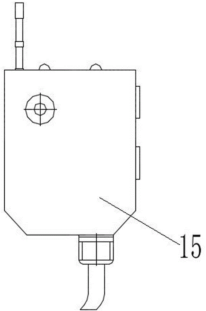
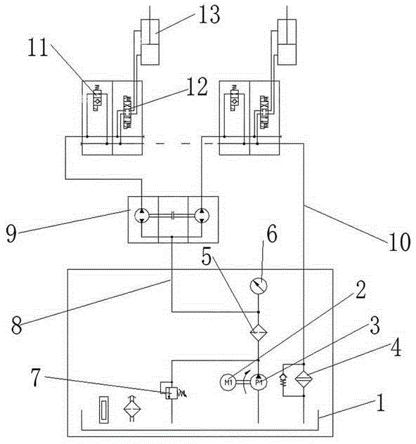
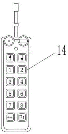
[0017] Attached below figure 1 , attached figure 2 , attached image 3 The present invention will be further described.

[0018] as attached figure 1 As shown, the mobile formwork template control system includes

[0019] The hydraulic station consists of a fuel tank 1, an oil pump 3 whose inlet is connected to the fuel tank 1 through a fuel pipe, a motor 2 installed on the oil pump 3, and a relief valve 7 connected to the outlet of the oil pump 3. The outlet of the oil pump 3 is connected through a filter 5 Pressure gauge 6 and oil inlet pipe 8; Hydraulic synchronous motor 9, its inlet end is connected with oil inlet pipe 8; The inlet port is connected to each outlet port of the hydraulic synchronous motor 9 , and the other inlet port is connected to the oil tank 1 through the oil return pipeline 10 . After the system pressure is adjusted through the overflow valve 7, the oil pump 3 operates after the motor 2 is started, and the hydraulic oil is extracted from the oil t...


PUM


Abstract

The invention relates to a control system for a movable formwork template. The control system comprises a hydraulic station and a hydraulic synchronous motor, wherein the hydraulic station consists of an oil tank, an oil pump, a motor and an overflow valve, the inlet end of the oil pump is connected into the oil tank through an oil pipe, the motor is mounted on the oil pump, and the overflow valve is connected to the outlet end of the oil pump; the outlet end of the oil pump is connected to a pressure gage and an oil inlet pipe through a filter; the inlet end of the hydraulic synchronous motor is connected to the oil inlet pipe. After the pressure of the system is adjusted through the overflow valve, the oil pump works after the motor is started to pump hydraulic oil from the oil tank and convey the hydraulic oil to the hydraulic synchronous motor through the oil inlet pipe, pressure oil is averagely distributed into a plurality of loops by the hydraulic synchronous motor for supplying at each reversing valve respectively, and the action of each template oil cylinder is controlled through the reversing valves; due to the fact that the hydraulic synchronous motor can guarantee that the flows of all the template oil cylinders are the same, template oil cylinders with longer travel can keep synchronous in mutual moving process, larger error and difference cannot be generated, and a template is prevented from being deformed or even damaged.

Description

technical field [0001] The invention relates to bridge construction mobile formwork technology, in particular to a mobile formwork formwork control system. Background technique [0002] The hydraulic system of the mobile formwork formwork realizes the opening and closing of the formwork system by controlling the action of the cylinder through the hydraulic valve. Multiple cylinders are required to simultaneously drive the overall movement of multiple groups of formwork on one side. The synchronous performance of the cylinder action, single action and linkage requirements, and ease of control and maintenance requirements. In the past, the hydraulic system was only regulated by a synchronous valve or a throttle valve, and the synchronization performance was poor. However, due to the short stroke of the mold opening cylinder, the synchronization error can be eliminated in each stroke of the cylinder, so the previous hydraulic system can barely meet the use requirements. If the...

Claims


Application Information

Patent Timeline
Patent Type & Authority Applications(China)
IPC IPC(8): F15B11/08F15B13/02
CPCF15B11/08F15B13/02
Inventor 刘兴峰王瑞王龙奉秘嘉川李文英关泽强雷江
Owner SHANDONG HENGKUN MACHINERY
Why Eureka
Try Eureka