Natural ventilation tunnel structure

A tunnel structure and natural ventilation technology, which is applied in tunnels, mines/tunnel ventilation, mining equipment, etc., can solve the problems of uncoordinated, power consumption and other high later costs and high costs, so as to reduce the impact on the environment and save tunnel construction and operating costs, reducing the effect of vertical spread of harm

Inactive Publication Date: 2015-01-28
SHANGHAI URBAN CONSTR DESIGN RES INST GRP CO LTD
View PDF5 Cites 8 Cited by
  • Summary
  • Abstract
  • Description
  • Claims
  • Application Information

AI Technical Summary

Problems solved by technology

However, the existing mechanical ventilation has the following deficiencies: first, to install ventilation equipment, the section of the tunnel is relatively high, and the project cost is high; At the tuyere, the concentration of air pollution is highly concentrated, which is difficult to meet the environmental protection requirements, and when there are residents living near the tunnel entrance, the tunnel exhaust gas is not allowed to be discharged concentratedly at the tunnel entrance
However, in the specific building construction, the layout of the ventilation shaft is often difficult to find a suitable layout position due to the restrictions of various conditions such as landscape, opposition from surrounding residents, planning, etc.
Therefore, if the existing tunnels want to adopt a natural ventilation structure, either the cost is very high, or the location of the layout is unreasonable, which is very inconsistent with the surrounding landscape. What's more, the natural ventilation effect of the tunnel may not be realized at all.

Method used


Image

  • Natural ventilation tunnel structure
  • Natural ventilation tunnel structure
  • Natural ventilation tunnel structure

Examples


Embodiment 1

[0030] The purpose of the present invention is achieved through the following technical solutions:

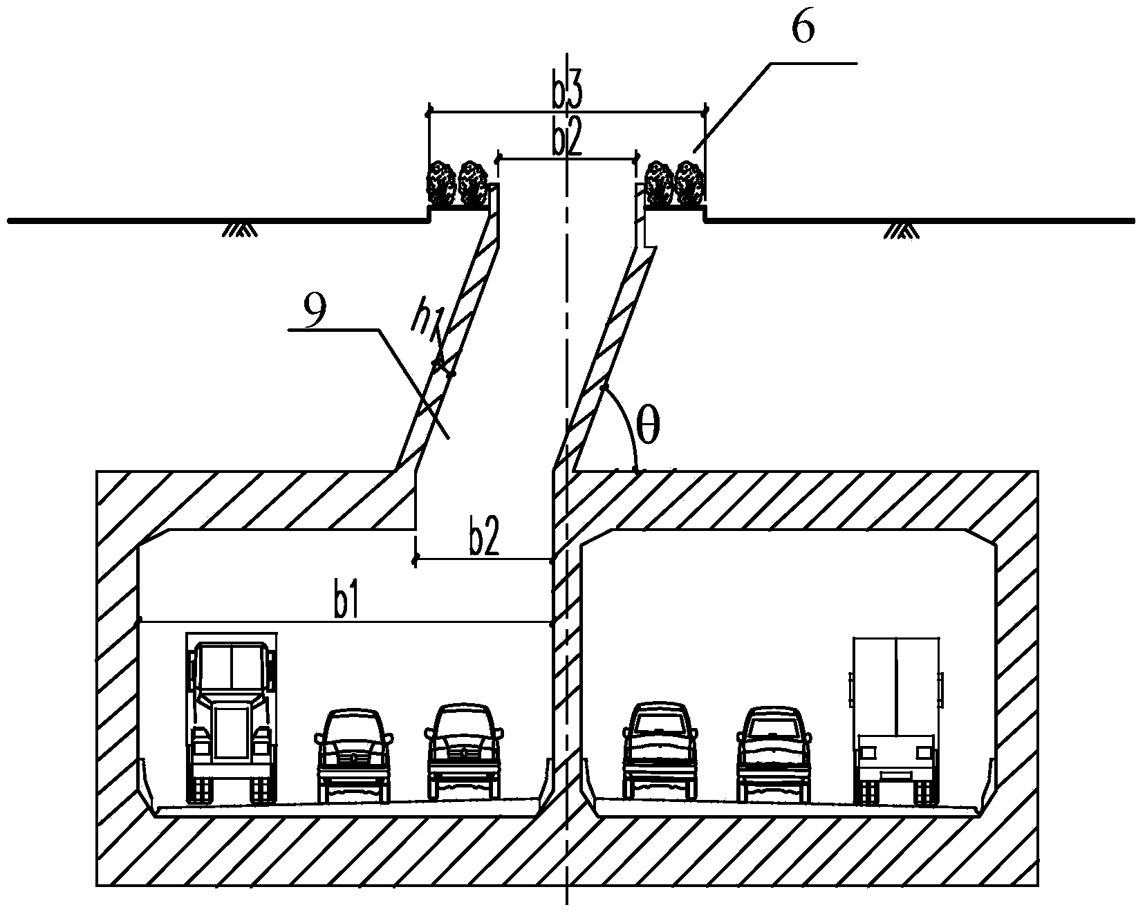
[0031] Combined with the actual situation of the engineering in the city, the ventilation shaft of the tunnel of the present invention is a ventilation shaft based on the median strip of the ground road. The section design form of the ventilation shaft is to open a ventilation inlet of a certain width on the top of the tunnel, and connect it obliquely to the ventilation opening in the central isolation zone of the road on the ground through the shaft shaft. The section of the ventilation shaft is parallelogram. This is more conducive to the rapid flow of air. This design utilizes the piston wind pressure generated by the vehicle running and the negative pressure at the bottom of the ventilation shaft to realize the natural ventilation of the tunnel, thus ensuring a good air environment in the tunnel.

[0032] The naturally ventilated tunnel of the present invention is a city a...

Embodiment 2

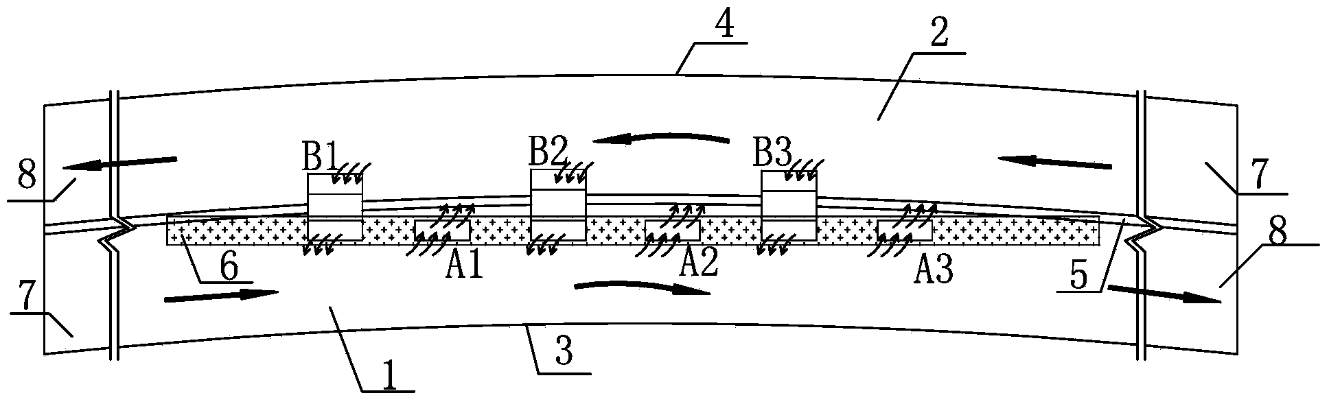
[0042] The difference between this embodiment and Embodiment 1 lies in that the center line of the central isolation zone in this embodiment is offset from the tunnel center line and the offset value exists. figure 2 with Figure 5 It shows the layout of ventilation shafts when the road median is inconsistent with the center line of the tunnel (oblique or curved intersection).

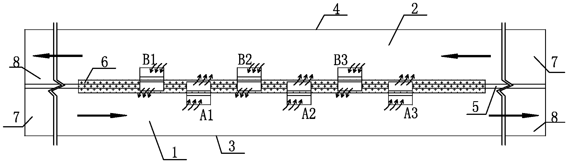
[0043] see figure 2 with Figure 5 , the tunnel body of the present invention can be a unidirectional urban tunnel with double tunnel holes known in the prior art, which includes: an uplink tunnel 1, a downlink tunnel 2, an uplink side wall 3, a downlink side wall 4, a middle partition wall 5, a road Central isolation zone 6, tunnel air inlet 7, tunnel air outlet 8, etc. What A1, A2, A3 represent respectively is the inclined ventilation shaft 9 that the interval of uplink tunnel is set (as Figure 5 Shown) the layout position of the air outlet; B1, B2, B3 respectively represent the inclined venti...

Embodiment 3

[0046] The difference between this embodiment and Embodiment 1 is that a wind cap can be added at the air inlet or outlet of each ventilation shaft to enhance the effect of ventilation and smoke exhaust. The hood is used to enhance the effect of exhausting or exchanging air. The setting method and structure of the hood can be realized by adopting the existing hood structure in the prior art.

[0047] Other parts of this embodiment are identical to Embodiment 1.

[0048] The invention solves the problem of arranging the ventilation shafts of long and large tunnels, especially urban tunnels, not only effectively realizes the natural ventilation of the tunnels, but also saves the construction and operation costs of the tunnels and ensures the safety of construction.

[0049] In addition, several ventilation shafts of the present invention are evenly spaced and arranged on the top of the tunnel along the length direction of the tunnel. By adopting this fragmented structure, the ...


PUM


Abstract

The invention discloses a natural ventilation tunnel structure. The natural ventilation tunnel structure comprises a tunnel body and a plurality of ventilation wells. The ventilation wells are arranged at intervals in the length direction of the tunnel body. Air inlets of the ventilation wells are communicated with the top wall of the tunnel body. Each ventilation well is provided with an air outlet. The air outlets are formed in a road middle isolation strip on the ground above the tunnel body, and the air outlets are formed at intervals in the length direction of the road middle isolation strip. According to the natural ventilation tunnel structure, the problem that ventilation wells of long and large tunnels, especially urban tunnels, are hard to arrange is solved, natural ventilation of the tunnel is effectively achieved, and the building and operating cost of the tunnel is saved. Meanwhile, disperse exhausting of waste gas can be achieved through the exhaust structure capable of breaking up the whole into parts, and pollution and influence of centralized exhausting to the environment are greatly reduced.

Description

technical field [0001] The invention relates to tunnel ventilation structures, in particular to a tunnel structure suitable for natural ventilation of long tunnels. Background technique [0002] In the tunnel, the driving vehicles will continuously emit harmful exhaust gas and smoke. When the concentration of harmful exhaust gas and smoke exceeds a certain value, it will cause harm to the drivers and passengers, affecting their health and driving safety. Therefore, maintain a good air condition in the tunnel It is a necessary condition for driving safety, and the purpose of ventilation is to reduce the harmful gas or pollutants in the tunnel to below the allowable concentration, so as to ensure the safety and comfort of driving, which is an important criterion for the service level of the tunnel. [0003] There are generally two ways of tunnel ventilation: natural ventilation and mechanical ventilation. However, the existing mechanical ventilation has the following deficien...

Claims


Application Information

Patent Timeline
Patent Type & Authority Applications(China)
IPC IPC(8): E21F1/18E21D9/14
CPCE21F1/003E21D9/14E21F1/18
Inventor 张银屏嵇中袁自鸣欧阳文彪姜弘林涛董驰斌黄丽君冯奇
Owner SHANGHAI URBAN CONSTR DESIGN RES INST GRP CO LTD
Why Eureka
Try Eureka