
Engine cover pneumatic telescopic supporting mechanism

Inactive Publication Date: 2017-05-17
CHONGQING DAIFA CASTING
View PDF7 Cites 2 Cited by
  • Summary
  • Abstract
  • Description
  • Claims
  • Application Information

AI Technical Summary

Problems solved by technology

[0004] The present invention intends to provide an engine hood pneumatic telescopic support mechanism to solve the problem of difficulty in arranging engine hood support rods due to insufficient layout space in the engine room

Method used


Image

  • Engine cover pneumatic telescopic supporting mechanism
  • Engine cover pneumatic telescopic supporting mechanism
  • Engine cover pneumatic telescopic supporting mechanism

Examples


Embodiment Construction

[0018] The present invention will be described in further detail below by means of specific embodiments:

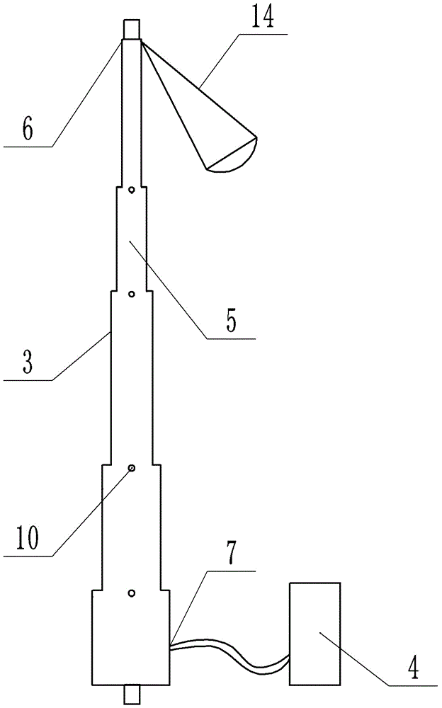
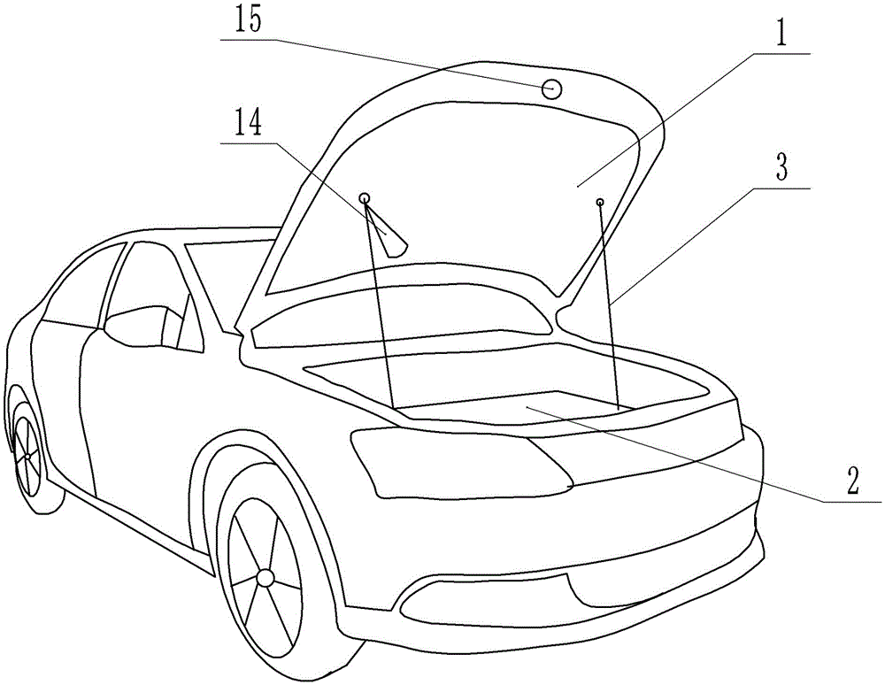
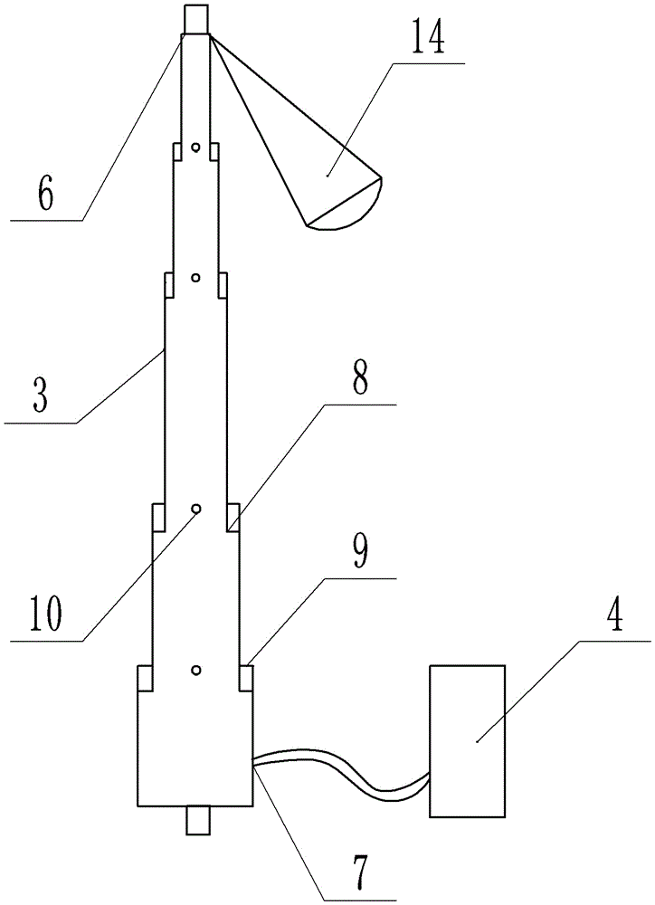
[0019] The reference signs in the drawings of the description include: engine cover 1, engine compartment 2, pneumatic telescopic rod 3, inflation device 4, single rod 5, air outlet 6, air inlet 7, inner shoulder 8, outer shoulder 9, Position slot 10, spring seat 11, spring 12, ball pin 13, LED lamp 14, button 15.

[0020] The embodiment is basically as attached Figure 1 to Figure 3 Shown: engine hood pneumatic telescopic support mechanism, including engine hood 1, engine compartment 2 and control mechanism, also includes pneumatic telescopic support device, pneumatic telescopic support device includes pneumatic telescopic rod 3 and inflation device 4, the two ends of pneumatic telescopic rod 3 are respectively The engine cover 1 and the engine compartment 2 are screwed together. The pneumatic telescopic rod 3 is formed by arranging several single rods 5 from top to bot...


PUM


Abstract

The invention discloses an engine cover pneumatic telescopic supporting mechanism and relates to the technical field of automobile manufacturing. The engine cover pneumatic telescopic supporting mechanism comprises an engine cover, an engine compartment and a control mechanism and further comprises a pneumatic telescopic supporting device. The pneumatic telescopic supporting device comprises a pneumatic telescopic rod and an inflation device. The two ends of the pneumatic telescopic rod are movably connected with the engine cover and the engine compartment respectively, the pneumatic telescopic rod is formed by arranging multiple single rods in the axial direction from top to bottom, the diameters of the single rods are gradually increased from top to bottom, every two adjacent single rods are connected in a sliding and sealed mode, the end, connected with the engine cover, of the pneumatic telescopic rod is provided with an air outlet, the end, connected with the engine compartment, of the pneumatic telescopic rod is provided with an air inlet, and the air inlet is connected to the inflation device. According to the structure, the pneumatic telescopic rod formed by the single rods is small in occupied area after shrinking, the problem that as an engine cover supporting rod is too large and too long, the position of a cabin is insufficient, and maintenance work is affected is avoided, and the structure is high in safety performance and convenient to operate.

Description

technical field [0001] The invention relates to the field of motor vehicle superstructure subassemblies. Background technique [0002] Generally, the engine hood support rod assembly is composed of a support rod and a support rod directly injected on the support rod. It is generally fixed in the engine compartment, but it is easy to appear that the support rod does not rotate smoothly when the fixed end is opened to support the engine hood. . [0003] In the prior art, the function of the automobile engine cover support rod is to support the engine cover through the engine cover support rod when the engine compartment needs to be checked; in the process of frequently opening the engine cover, the engine cover support rod will bear a larger moment , or when the user suddenly applies a certain pull-down acceleration or pull-down force to the engine cover without putting down the engine cover support rod, the engine cover support rod will also bear a large force. If the engine...

Claims


Application Information

Patent Timeline
Patent Type & Authority Applications(China)
IPC IPC(8): B62D25/12
CPCB62D25/12
Inventor 唐利
Owner CHONGQING DAIFA CASTING
Learn More