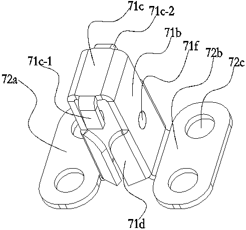
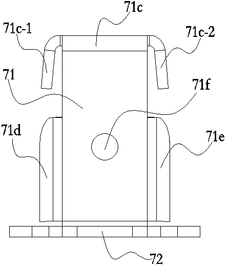
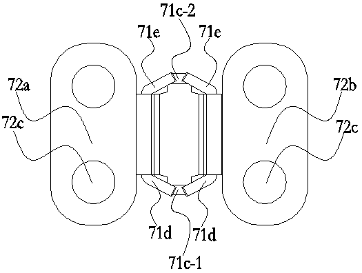
Stand column with bottom connected with foot plate support

A footboard and column technology, which is applied in the field of uprights connected with footboard frames at the bottom, can solve the problems of being exposed to the outside, long construction time, and affecting the appearance of the guardrail, so as to avoid bending under force and increase the connection strength.

Inactive Publication Date: 2015-01-28
DAJUN BUILDING MATERIALS
View PDF6 Cites 0 Cited by
  • Summary
  • Abstract
  • Description
  • Claims
  • Application Information

AI Technical Summary

Problems solved by technology

[0002] Existing guardrail usually comprises column, horizontal tube and handrail, and the cross-section of column is circular or rectangular usually, and column and horizontal tube, the connection mode of column and handrail usually has two kinds: a kind of is to adopt welding connection, and this connection mode The advantage is that the connection is firm, but the construction time is long and the input cost is high; the other is to fix it with bolts through T-shaped connectors. Since the existing guardrails are mostly made of metal and have been exposed for a long time, the connection between the column and the handrail The connection between the column and the horizontal pipe is easily damaged due to rust, and the bolts (or screws) are exposed to the outside, which affects the appearance of the guardrail

Method used


Image

  • Stand column with bottom connected with foot plate support
  • Stand column with bottom connected with foot plate support
  • Stand column with bottom connected with foot plate support

Examples


Embodiment Construction

[0017] The present invention will be further described in detail below in conjunction with the accompanying drawings.

[0018] In the description of the present invention, it should be understood that the terms "upper", "lower", "front", "rear", "left", "right", "vertical", "top", "bottom" " The orientation or positional relationship indicated by "inside", "outside", "etc. is based on the orientation or positional relationship shown in the perspective view in the accompanying drawings, and is only for the convenience of describing the present invention and simplifying the description, rather than indicating or implying the indicated device. Or elements must have a particular orientation, be constructed and operate in a particular orientation, and therefore should not be construed as limiting the invention.

[0019] Furthermore, the terms "first", "second", "third", "fourth" and "fifth" are used for descriptive purposes only and should not be construed to indicate or imply rela...


PUM


Abstract

The invention relates to a stand column with the bottom connected with a foot plate support. The stand column comprises a stand column body and the foot plate support, the stand column body is of a hollow structure, and the cross section of the stand column body is octagonal; the foot plate support comprises a foot plate connecting part used for being connected with the stand column body and a foot plate fixing part which is located at the lower portion of the foot plate connecting part and used for being connected with a guard bar installation face; the foot plate connecting part is arranged on the inner side of the bottom of the stand column body and is in close fit with the inner wall of the stand column body. The bottom of the stand column body can be conveniently connected to the guard bar installation face, and the foot plate connecting part of the foot plate support extends to the inner side of the bottom of the stand column body; as the foot plate connecting part has a certain height, parts, used for connection, of the stand column body and the foot plate support are increased, the connecting strength between the stand column body and the foot plate support is increased, and the stress bending of the stand column body is effectively avoided.

Description

technical field [0001] The invention relates to the field of building materials, in particular to a column with a foot plate frame connected at the bottom. Background technique [0002] Existing guardrails usually include uprights, horizontal tubes and handrails. The cross-section of the uprights is usually circular or rectangular. There are usually two ways of connecting the uprights and the horizontal tubes, and the uprights and handrails: one is to use welded connections. The advantage is that the connection is firm, but the construction time is long and the investment cost is high; the other is to fix it with bolts through T-shaped connectors. Since the existing guardrails are mostly made of metal and exposed for a long time, the connection between the column and the handrail is made. At the same time, the connection between the column and the horizontal tube is easily damaged due to rust, and the bolts (or screws) are exposed to the outside, which affects the beauty of ...

Claims


Application Information

Patent Timeline
IPC IPC(8): E04F11/18
Inventor 田大军
Owner DAJUN BUILDING MATERIALS
Why Eureka
Try Eureka