Aerated concrete block production system

A technology of aerated concrete and production system, applied in ceramic molding workshops, auxiliary molding equipment, ceramic molding machines, etc., can solve the problems of shortening the service life of feeding devices, increasing costs, waste of raw materials, etc., to improve production efficiency, avoid Winding, cost reduction effect

Inactive Publication Date: 2015-01-28
广安世宇建筑材料有限公司
View PDF8 Cites 9 Cited by
  • Summary
  • Abstract
  • Description
  • Claims
  • Application Information

AI Technical Summary

Problems solved by technology

[0005] 1. The structure of the batching tank is not reasonable enough. After the raw materials are added to the batching tank, they are easy to condense on the inner wall of the batching tank, so that the mixing of raw materials is insufficient and the proportion is uneven, which affects the normal operation of the equipment, wastes raw materials, cannot guarantee product quality, and increases costs;
[0006] 2. During the batching process, it is strongly vibrated by the batching tank, the feeding accuracy is reduced, and the service life of the feeding device is shortened;
[0007] 3. There are defects in the body transportation device after cutting, which leads to large waste and low production efficiency;
[0008] 4. The billet making process of aerated concrete is time-consuming and laborious, and the production efficiency is low, which is not conducive to industrial production;
[0009] 5. A large amount of waste generated in the production process of aerated concrete blocks is not recycled in time, the recycling efficiency is low, the recycling rate of waste is not high, and the waste of raw materials is serious;
[0010] 6. During the production process of aerated concrete blocks, a large amount of waste gas and waste residue are generated, which pollute the environment after being discharged directly

Method used


Image

  • Aerated concrete block production system
  • Aerated concrete block production system
  • Aerated concrete block production system

Examples


Embodiment Construction

[0062] The present invention will be further described below in conjunction with the embodiments and accompanying drawings.

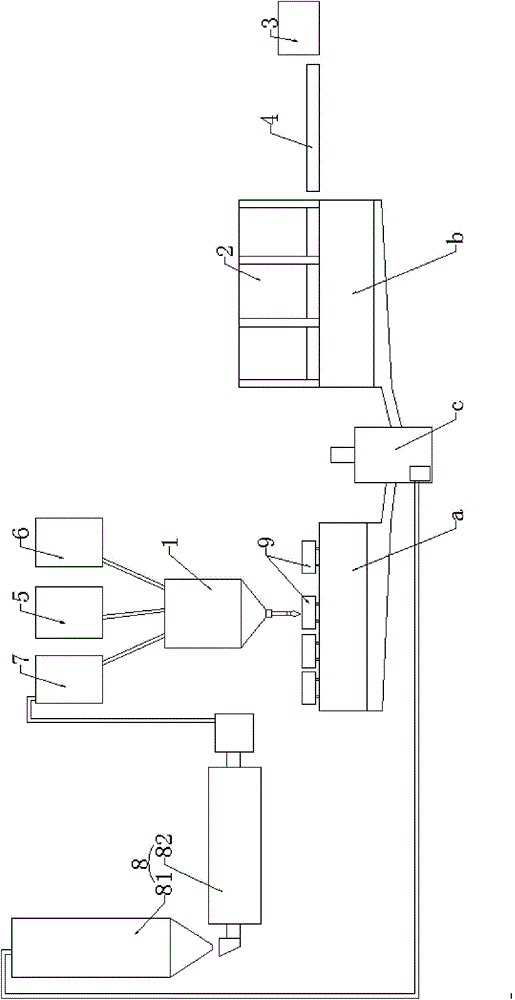
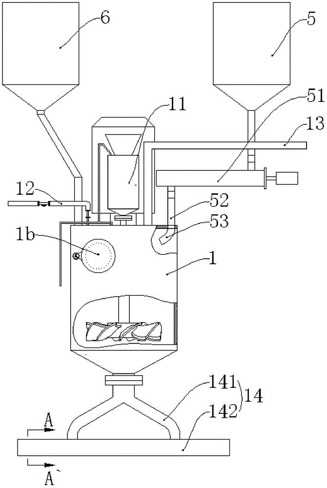
[0063] Such as Figure 1 to Figure 17 As shown, a production system for aerated concrete blocks includes a batching tank 1, an aerated concrete block cutting machine 2 and an autoclave 3, wherein a material is arranged between the batching tank 1 and the aerated concrete block cutting machine 2 A slurry forming transfer mechanism, a block transport mechanism 4 is provided between the aerated concrete block cutting machine 2 and the autoclave 3, and the top of the batching tank 1 communicates with the lime storage tank 5 and the cement storage tank 6 respectively , a grouting pool a is provided directly below the batching tank 1, a cutting pool b is provided directly below the aerated concrete block cutting machine 2, and between the grouting pool a and the cutting pool b A recovery pool c is provided, the grouting pool a and the cutting pool b communic...


PUM


Abstract

The invention discloses an aerated concrete block production system. The aerated concrete block production system comprises a make-up tank, an aerated concrete block cutting machine, a still kettle, a slurry forming and delivering mechanism and a block transport mechanism, wherein the slurry forming and delivering mechanism is arranged between the make-up tank and the aerated concrete block cutting machine, the block transport mechanism is arranged between the aerated concrete block cutting machine and the still kettle, the make-up tank is communicated with a lime storage tank and a cement storage tank respectively, a grouting tank is arranged right below the make-up tank, a cutting tank is arranged right below the aerated concrete block cutting machine, the grouting tank and the cutting tank are communicated with a recycling tank, a recycling material tank is arranged above the make-up tank and is connected with the recycling tank via a circulating device and then communicated with the make-up tank. The aerated concrete block production system has the advantages that the structure of the make-up tank is optimized, feeding of raw materials is accurate, the raw materials are sufficiently and uniformly mixed, automatic and industrialized production is realized, various waste generated during production can be timely and comprehensively recycled, energy is saved, the environment is protected, and no slag and waste gas are discharged to cause environment pollution.

Description

technical field [0001] The invention relates to the production field of aerated concrete blocks, in particular to an aerated concrete block production system. Background technique [0002] my country is a country with energy shortage and high energy consumption at the same time. Building energy consumption accounts for about 30% of the total energy consumption of the society. Therefore, building energy conservation plays an important role in implementing the scientific development concept, implementing energy conservation and emission reduction strategies, and building a conservation-oriented society. The realization of sustainable development is of great significance. In view of this, the country promulgated the "Design Standard for Energy Conservation of Public Buildings" (GB50189-2005) in 2005. In order to better implement the national energy-saving standards and fully realize the goal of building energy-saving 50%, government departments across the country clearly require...

Claims


Application Information

Patent Timeline
IPC IPC(8): B28B15/00B28B17/00
CPCB28B15/00B28B17/00
Inventor 蒋昆蒋东易
Owner 广安世宇建筑材料有限公司
Why Eureka
Try Eureka