
Grinding Fixtures for Support Plates

A support plate and grinding technology, which is applied in the direction of grinding the workpiece support, etc., can solve the problems of support plate clamping difficulty, cumbersome clamping operation, low work efficiency, etc., achieve simple operation, shorten the time required for clamping, The effect of easy operation

Active Publication Date: 2017-03-22
天津市中马骏腾精密机械制造有限公司
View PDF5 Cites 0 Cited by
  • Summary
  • Abstract
  • Description
  • Claims
  • Application Information

AI Technical Summary

Problems solved by technology

[0003] However, during grinding, it is difficult to clamp such a support plate. Usually, it is necessary to operate a variety of clamping members for clamping and fixing, so that the clamping operation is cumbersome and the work efficiency is low.

Method used


Image

  • Grinding Fixtures for Support Plates
  • Grinding Fixtures for Support Plates
  • Grinding Fixtures for Support Plates

Examples


Embodiment Construction

[0023] Next, a grinding jig for a support plate as an example of the present invention will be described based on the drawings.

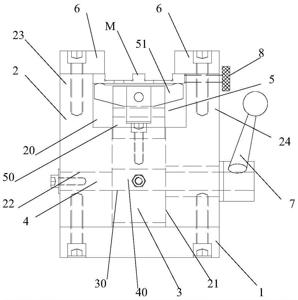
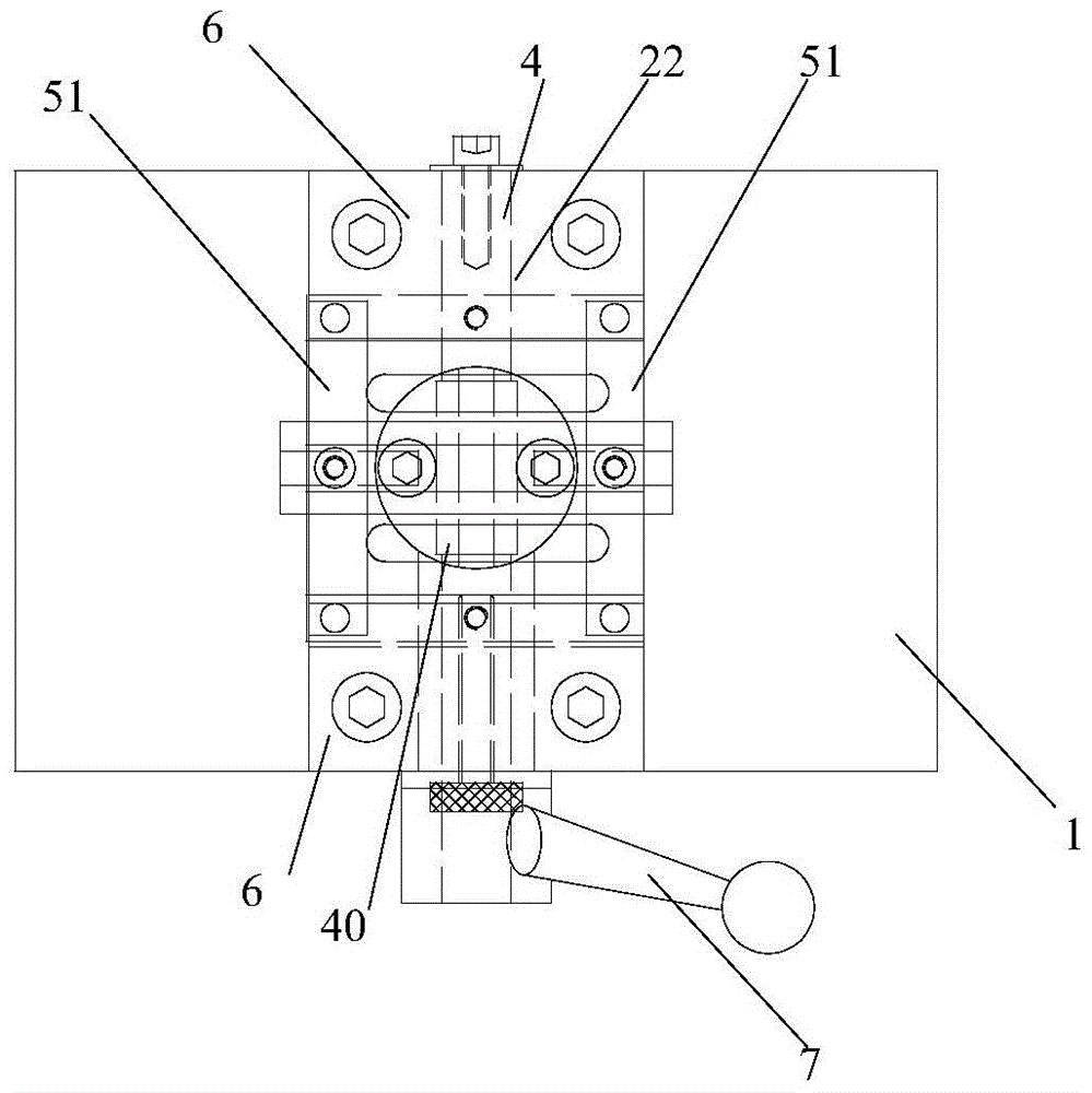
[0024] figure 2 It is a schematic front view showing the grinding jig of the support plate of this invention. image 3 It is a plan view schematic diagram which shows the grinding jig of the support plate of this invention. Figure 4 It is a front schematic diagram which shows the slider of the grinding jig of the support plate of this invention. Figure 5 It is a side view schematic diagram which shows the slider of the grinding jig of the support plate of this invention. Image 6 It is a front schematic diagram which shows the bracket of the grinding jig of the support plate of this invention. Figure 7 It is a plan view schematic diagram which shows the bracket of the grinding jig of the support plate of this invention. Figure 8 It is a schematic front view showing the swing frame of the grinding jig of the support plate of this invention. ...


PUM


Abstract

The invention provides a support plate grinding fixture, which is provided with an oblong bottom plate, a body, a slide block, an eccentric shaft, a support plate support base, stop blocks and a handle, wherein the body is arranged on the bottom plate, the upper end of the body is provided with a through groove by processing, the bottom of the through groove is provided with a slide block through hole which penetrates through the body in the vertical direction, and in the middle part of the body, an eccentric shaft hole which penetrates through the body is formed in the direction vertical to the extension directions of the through groove and the slide block through hole; the slide block is arranged in the slide block through hole; the eccentric shaft is provided with an eccentric cam, and the eccentric cam is positioned in a connection through hole when the eccentric shaft is inserted into the eccentric shaft hole and the connection through hole of the slide block; the support plate support base is positioned in the through groove of the body, and is provided with a connection frame which is connected with the upper end of the slide block in the vertical direction, and supporting plates which are connected to two ends of the connection frame, and the support plate is supported by virtue of the two supporting plates; the stop blocks are arranged on a first upper end part and a second upper end part, which form the through groove, of the body, and can stop the edges of the support plate; the handle is connected with the eccentric shaft.

Description

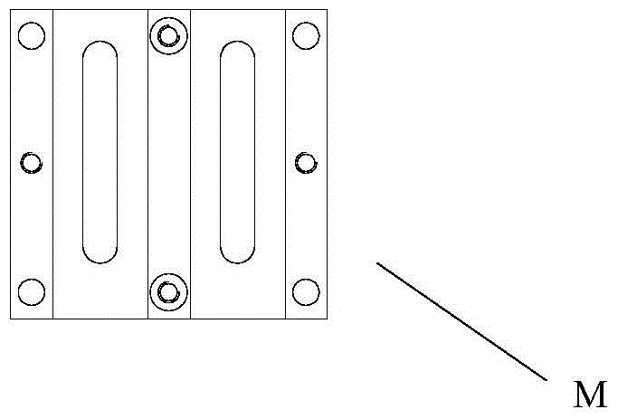
technical field [0001] The invention relates to a fixture, in particular to a grinding fixture for a support plate. Background technique [0002] Currently, sometimes installation users request processing such as figure 1 As shown in the support plate, the support plate includes a bottom plate and three elongated bosses formed on the bottom plate at a distance. After processing such a support plate, according to customer requirements, the upper surface of the bottom plate and the bosses need to Grinding is performed. [0003] However, it is relatively difficult to clamp such a support plate during grinding, and it is usually necessary to operate multiple clamping members for clamping and fixing, so that the clamping operation is cumbersome and the work efficiency is low. Contents of the invention [0004] The present invention is proposed in view of the problems existing in the prior art, and its purpose is to provide a grinding jig for clamping a support plate which is ...

Claims


Application Information

Patent Timeline
Patent Type & Authority Patents(China)
IPC IPC(8): B24B41/06
CPCB24B41/06
Inventor 杜辰张钧王文春安明
Owner 天津市中马骏腾精密机械制造有限公司
Learn More