Clutch bearing groove rib manipulator

A manipulator and clutch technology, applied in the field of forging, to reduce the difficulty of debugging equipment and improve the efficiency of forging production

Active Publication Date: 2015-01-28
ZHEJIANG ZHONGJI FOUNDRY & FORGING
View PDF5 Cites 0 Cited by
  • Summary
  • Abstract
  • Description
  • Claims
  • Application Information

AI Technical Summary

Problems solved by technology

[0003] The object of the present invention is to solve the deficiencies of the prior art, and provide a clutch bearing groove rib manipulator, which moves to the groove position through the guide slope of the manipulator when the workpiece is ejected during the forging process, and the rib blocks the workpiece in the forging process. Inside the manipulator, the workpiece will not turn over in the manipulator, fly out of the manipulator, or drop the workpiece, thereby improving forging production efficiency and reducing the difficulty of debugging equipment

Method used


Image

  • Clutch bearing groove rib manipulator
  • Clutch bearing groove rib manipulator
  • Clutch bearing groove rib manipulator

Examples


Embodiment Construction

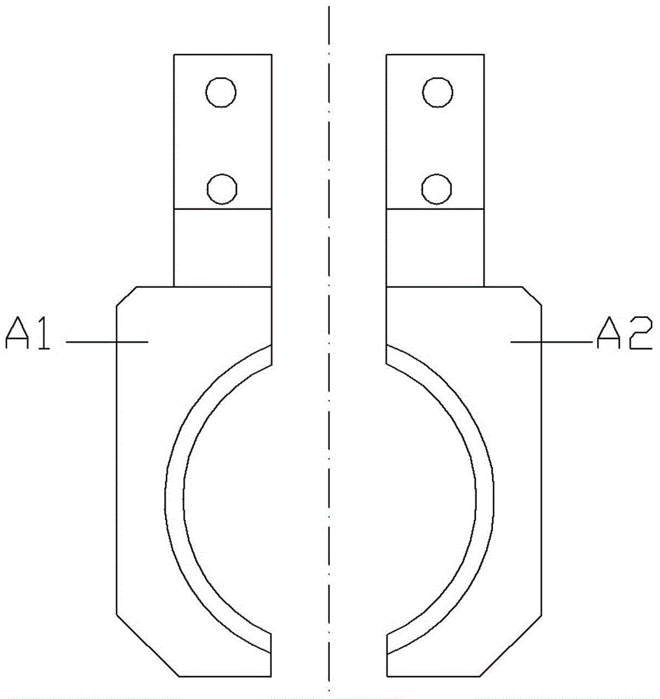
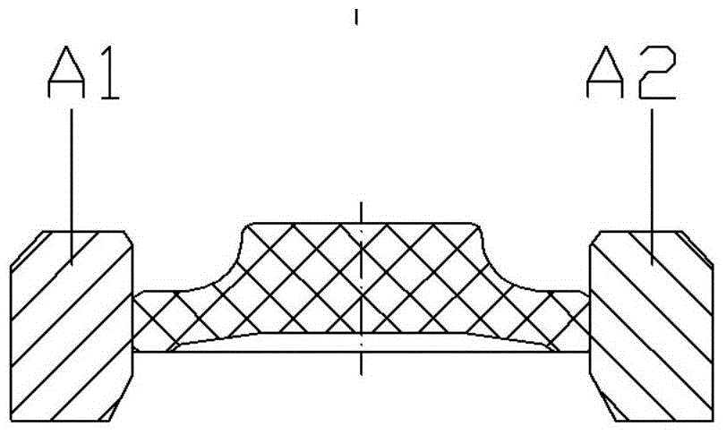
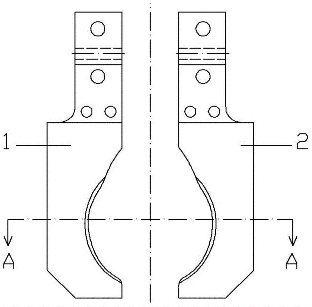
[0015] Example: see Figures 3 to 5 As shown, the clutch bearing groove rib manipulator includes the left clamp arm 1 and the right clamp arm 2 of the manipulator, the left clamp arm 1 and the right clamp arm 2 are symmetrical structures, and the clamping surface of the left clamp wall 1 is from top to The bottom is sequentially formed with a guiding slope 11, a homeopathic slope 12, a clamping straight surface 13 and a sidewall step surface 14, and the clamping surface of the right clamping wall 2 is sequentially formed with a right clamping arm guiding slope 21 and a right clamping surface from top to bottom. Arm along the inclined surface 22, the right clamping arm clamping straight surface 23 and the right clamping arm rib step surface 24, the guiding inclined surface 11 is inclined to the lower right, and the inclined surface 12 is inclined to the lower left.

[0016] The included angle a between the guide slope 11 and the vertical line L is 10 degrees.

[0017] Working ...


PUM


Abstract

The invention relates to a clutch bearing groove rib manipulator, which comprises a left clamping arm and a right clamping arm of the manipulator, wherein the left clamping arm is symmetrical with the right clamping arm, the clamping surface of the left clamping arm is sequentially provided with a guide inclined surface, a following inclined surface, a clamping straight surface and a rib step surface from top to bottom, the clamping surface of the right clamping arm is sequentially provided with a guide inclined surface, a following inclined surface, a clamping straight surface and a rib step surface from top to bottom, the guide inclined surface of the left clamping arm is inclined to the right lower part, and the following inclined surface of the left clamping arm is inclined to the left lower part. The clutch bearing groove rib manipulator has the advantage that in the forging process, when a workpiece is jacked out, the workpiece is moved to the position of the groove by virtue of each guide inclined surface of the manipulator, and the workpiece is retained in the manipulator through a rib, so the workpiece is prevented from turning in the manipulator, flying out of the manipulator, or falling off, the forging production efficiency is improved, and the debugging difficulty of equipment is decreased.

Description

Technical field: [0001] The invention relates to the technical field of forging, in particular to a clamping manipulator used for producing clutch bearing workpieces. Background technique: [0002] See figure 1 As shown, the manipulator currently used in the production of OG19 clutch bearings is composed of the left jig arm A1 and the right jig arm A2, and the workpiece is clamped between the left jig arm A1 and the right jig arm A2. The surface for clamping the workpiece is a flat surface, so it is prone to unstable workpiece clamping, workpiece drop, and workpiece flipping during the forging process. When the workpiece is ejected, the workpiece is easy to fly out of the manipulator, resulting in long downtime for debugging and low production efficiency. Invention content: [0003] The object of the present invention is to solve the deficiencies of the prior art, and provide a clutch bearing groove rib manipulator, which moves to the groove position through the guide slo...

Claims


Application Information

Patent Timeline
Patent Type & Authority Applications(China)
IPC IPC(8): B21J13/10B25J15/08
CPCB21J13/10B25J15/08
Inventor 王峰薛晶求跃明
Owner ZHEJIANG ZHONGJI FOUNDRY & FORGING
Why Eureka
Try Eureka